Ok, now to be a bit more serious, let me tell y'all a story. Got two B1K boards and transistors in the other day. Did all the mounting of the parts, and made a mistake that probably means I need new transistors. Yah, I put ALL of the transistors in the K positions instead of the correct J positions! Yah, applied voltage and at that moment (after neither B1K board would work) I felt like a fool. Getting the transistors back out is a crap shoot. So having done all that and 'carefully' placing the transistors in the correct J positions, I tested again. Of course, I had no confidence that anything would work. Test points T1, 3 and 4 are great. T5 and 6 are at zero volts, and T7 and 8 are both at 21 volts. T7 and 8 are NOT able to be adjusted by the pots.
Filaments show .7 ohms so there is continuity.
I am guessing that the first step is just to buy 2 new boards for the transistors and start there.
Filaments show .7 ohms so there is continuity.
I am guessing that the first step is just to buy 2 new boards for the transistors and start there.
The voltage drop across each R1 resistor is .97 volt. The value of these resistors measures between 95-100 ohms, but the bands say 150 ohms. My fault for not raising one leg for measurement. Thank you for your quick reply. BTW yes, both boards were powered up. So this is where we are at. I'm just trying to move forward from this mess.
Lastly, no the Korg filament is not lit.
Lastly, no the Korg filament is not lit.
Yes, in fact I have looked closely at the filament with good lighting and magnification. Seeing how microscopic that the filament is, It bears another look. Something like that can actually look to be intact, but it is not. I'd rather that weren't the case when a new tube costs as much as it does. I will get to it and let you know.
This is a real help to me, and I am grateful.
So, I looked very closely at the filament and as I looked, I did a tap test. This helps bring out the break of a filament, even when it looks good by eye. So it passed, and now I am considering your latest statement about the actually rising voltage at T5 and 6 in absence of the filament. The fact that this circuit is simple will hopefully make it easier to troubleshoot, so that is encouraging.
For tonight I am done, but eager to check these things out in the morning. I will sleep on it.
When get back to it, check the following:
1. confirm that the 475R resistors are correct
2. confirm the solder joints of the filament pins of the Nutube and the 475R resistors are good
3. confirm that 9V is at the 475R resistors (opposite side from T5, T6)
4. measure the voltage across the 475R resistor. If the filament is conducting and all of the solder joints are good, the resistor should drop about 8.5V
The JFE2140 seems like a good catch! Could it be a suitable replacement for the 2SK170? I am anxiously awaiting the outcome of the hearing!For a while now i was feeling that this project is ripe for smd version, and i had an itch yesterday and drew it up. Semi smd, caps are trough hole (nichicon uhw are unbeatable for this preamp, 1800uf, so almost double capacity) and 5W 270R resistor, still not feeling like leaving my fingerprints on it 😅 Coupling caps are MU (acrylic film) as @tamra used in his build, i'm a big proponent of that cap, really really good for such a small little bugger (but can leave a pad for 10uf silmics if someone prefers them over film). Jfet buffers are jfe2140, factory matched, good and cheap (no need to get many to match, wasting time and money). I've included Mark's smps filter on board, but i'll probably remove in final version as my smd version of it is such a small footprint it can easily fit on the side of the case. Only benefit here is bigger cap for the smps filter, which can improve performanse, but can also trigger some smps supplies to not start, so i find regular 470uf uhw pair are enough. Current dimension is 65x80mm, drastically smaller, and it will be even less in final version. Another benefit of smd is ground pour (plane). I'll be designing a flexi connector for nutube itself to isolate it from board as well. As usual, i'll build and test first, then leave files here like with my previous custom b1k board.
1) Yes, the 475k resistors are correct (I had my doubts as well!)
2) Although the solder joints 'look good', I will reflow them.
3) Yes, there is exactly 9 volts at this point.
4) No, there is no voltage drop occurring. That's a bad thing huh.
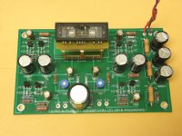
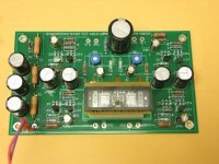
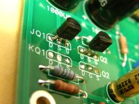
I am including a few photos that might help.
One more observation. The 3 watt 270 ohm resistor is hot, at 150F.
2) Although the solder joints 'look good', I will reflow them.
3) Yes, there is exactly 9 volts at this point.
4) No, there is no voltage drop occurring. That's a bad thing huh.
I am including a few photos that might help.
One more observation. The 3 watt 270 ohm resistor is hot, at 150F.
Attachments
I have plenty of the J113's with bias resistors from the DIYStore, I use K170's in place of half the J113's in these projects. Send me a PM with your address and how many you need and I will send them in the mail to you.I am guessing that the first step is just to buy 2 new boards for the transistors and start there.

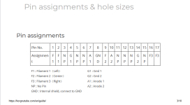
Pete connected both far end pins (which is as should be). He could have connected gnd in mid as well but it works the same.
I would start by reflowing.
@Deenoo yes, do note it is a dual package. It's quite a real deal, and yes there is better jfet (lsk389) but it is way too expensive (more than twice the price). I'll let you know how it sounds, but it is not a top of my list of priorities atm, might sell my old custom b1k on steroids to fund this one though.
Ok so I decided that I would lift the leg on the 475k resistor, and of course, I get the 9 volts on one end, and now I see the drop to 8.5 volts on the far end of the resistor. It wouldn't be a defect in the board, would it? I will check further. OTOH, I have a ballpeen hammer just within my reach...
I don't know whether to laugh or cry but THANK YOU! Am I that far gone? Ok, putting the ballpeen hammer back on the shelf now. It (the answer) was right in front of my freaking face. I may have to turn in my driver's license and voting card in the morning. Thank you for your patience. You saved a couple of circuit boards from getting smashed.


- Home
- Amplifiers
- Pass Labs
- B1 with Korg Triode