The V00 that I posted was a carbon copy of your schematics.
The second stage bias is roughly determined by the drain resistor of the JFET and the source resistor of the MOSFET.
i.e. about a factor of 10.
Since you were using 2x J270 / PF5102, Idss can be as high as 20mA.
That is why in the V00, the front end has 15mA bias, resulting in 150mA for the MOSFETs.
But that is only due to the model used and one can certainly change the Vto to get the bias as you want.
In the V0 model using 2SK170/2SJ74, the bias is "normal" -- 4mA for JFETs and 26mA for MOSFETs.
But as I said before, the effect of the base resistors may just be a Spice phenomena and may not be real .....
Patrick
Yes, you are right. That would explain the vastly different bandwidth results from both circuits. At comparable currents, the PF5102/J270 should have lower bandwidth then, need to check that.
The BJTs really act as grounded base amplifiers, so a gate resistor may reduce the bandwidth. I am no expert on grounded base amplifiers, though.
I built your servo into the model as I want to see what it does in the presence of a signal.
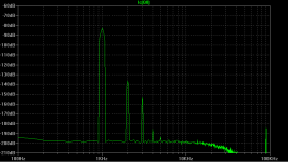
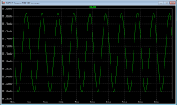
You can see in the attachment the FFT of the current through one of the NPN transistors.
A signal dependent AC current is clearly visible (11.7+/-0.1mA), and it has quite some 2nd & 3rd harmonics.
The explanation is quite simple.
Even the LP filter keeps the base voltage constant, the Vce variations will modulate the collector current.
Different to a current limiter, this servo has a constant bias in order to work in both directions.
So it is always in action, and its non-linearity will be seen by the rest of the circuit.
The even harmonics will cancel in the balanced circuit, but not the odd.
And this current has to be supplied by the output of the input stage.
FFT of the output indicates that distortion increases in the presence of this servo by about 6dB.
Not a major concern, but I personally would rather do proper thermal management so that I can get rid of any servo altogether.
Not meant to be a criticism by any means.
Just hoping for some open-minded discussions.
Patrick
.
Attachments
Been a while.
Finally I got some FDP5N50.
And I already have FqP3N80 & FQP3P50 for another reason.
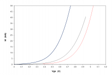
So here is a comparison after curve tracing.
Blue is FQP3P50, black is FQP3N80, red is FDP5N50.
I think actually FQP3N80 is closer with Vgs to the P-Ch. than FDP5N50.
Hardly any difference in transconductances (163mS, 160mS, 169mS respectively).
Patrick
.
Finally I got some FDP5N50.
And I already have FqP3N80 & FQP3P50 for another reason.
So here is a comparison after curve tracing.
Blue is FQP3P50, black is FQP3N80, red is FDP5N50.
I think actually FQP3N80 is closer with Vgs to the P-Ch. than FDP5N50.
Hardly any difference in transconductances (163mS, 160mS, 169mS respectively).
Patrick
.
Attachments
After a 4 year delay, the F5X-HV is finally finished.
Supply rails are +/-250V, and bias is 70mA per channel.
Differential output signal is at 1kHz into 150p load (as in a Stax headphone).
Output ___H2 ___H3
40Vrms -114dB -100dB
80Vrms -108dB -89dB
120Vrms -108dB -83dB
160Vrms -105dB -78dB
Measurements were done using an Audio Precision 2722.
Distortion levels meet expectation.
Especially one can see how effective the even harmonic cancellations, due to good matching.
Patrick
.
Attachments

Patrick, this is a fantastic piece of work, congratulations!
Thats a nice amount of power dissipation however, 70W (250V x 0,07A *2 (pos and neg) *2 (for both channels), I guess this wins the competition for output power to power dissipation ratio
Well it is negative temp in Munich and snow outside, so that would certainly help....
Just now (~1 week ago) I finished my new preamp which has the X5HV modules inside as well, 8 years in the making - finally I get to listen to what I was building back then, and what got this thread started. It does sound very nice
Did you try yours with a headphone? I am curious to know if the higher bias current is making a difference.
In fact, with this level of standing current, it might be appropriate for an electrostatic speaker, although the voltage levels might not be sufficient given the larger distances membrane - stators.
At some point I was considering building electrostatic supertweeters (10kHz up) with a little 3D printed horn, where this amplifier came in handy.... guess it will take another 8 years or so....
Of course Sorry for the delay, we had a online wine tasting this evening (hosted by the german magazine ZEIT, and themed around Beethoven) which was very nice.....
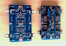
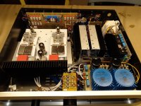
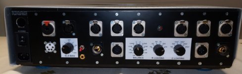
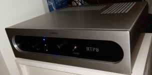
Here you can see the preamp front and back, it is fully symmetrical as is the X5HV, along with a nice teflon socket for the STAX headphone and adjustable polarisation voltage. The phono stage is the RTP5 circuit from Allan Wright / Vacuumstate, and the line stage is the same as Acoustic Research AR25. The coupling caps are Jantzen Silver caps and the RIAA caps are Military NOS KS caps from Siemens, that I recovered when my father passed away and we cleaned up the house, years ago.
The inside picture shows the phono and line stage on the left side, built on white teflon boards, and the headphone amplifier is the same as it was 5 years ago, mounted into the chassis vertically so the hot air can drift upwards.
Hope you like it!
Sorry for the delay, we had a online wine tasting this evening (hosted by the german magazine ZEIT, and themed around Beethoven) which was very nice.....Here you can see the preamp front and back, it is fully symmetrical as is the X5HV, along with a nice teflon socket for the STAX headphone and adjustable polarisation voltage. The phono stage is the RTP5 circuit from Allan Wright / Vacuumstate, and the line stage is the same as Acoustic Research AR25. The coupling caps are Jantzen Silver caps and the RIAA caps are Military NOS KS caps from Siemens, that I recovered when my father passed away and we cleaned up the house, years ago.
The inside picture shows the phono and line stage on the left side, built on white teflon boards, and the headphone amplifier is the same as it was 5 years ago, mounted into the chassis vertically so the hot air can drift upwards.
Hope you like it!
Attachments
So I guess my build looks a lot more like done with a hot needle, while your builds are admirably beautiful..... Sigh.... Its rather a prototype, modified in action and upgraded while building, and it works fine, so I am ok with it
By the way, next in line is my F5X, with the kit sitting in the basement, waiting for me to finally go for it!
By the way, next in line is my F5X, with the kit sitting in the basement, waiting for me to finally go for it!
Morde just finished his in record time and is totally satisfied.
He has reduced bias to 1.5A to keep heatsink temperature lower.
F5X -- the EUVL Approach - The Build Thread
Also some dual diodes to try.
Contact him direct for details / rectifier PCBs.
Patrick
He has reduced bias to 1.5A to keep heatsink temperature lower.
F5X -- the EUVL Approach - The Build Thread
Also some dual diodes to try.
Contact him direct for details / rectifier PCBs.
Patrick
- Home
- Amplifiers
- Pass Labs
- X5HV - the F5 principle applied to a headphone amp