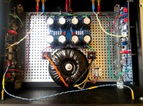
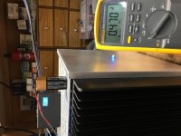
I did post some pictures before, but the latest one, with the mains hidden under the bottom plate, attached here again. And I did see your super nice build before too. This arrangement, though, does bring toroid closer to the input wires (and this nice shiny and expensive shielded toroid does help with that, of course), so there are compromises everywhere 🙂
Now, I did not change the 0.47ohm resistors. They look pretty fine and on the right side they were never exposed to any high temperature even theoretically. And I measure nice and stable voltages of 0.398-0.402 accross them all.
As of JFETs, there is always a chance I could damage them while handling and soldering somehow (both sides though?). If that would be my first build, I would definitely be calling myself a wretched builder and would start resoldering everything immediatelly. But as all the other builds went smoothly without any troubles I do have (too much?) confidence in myself already 🙂
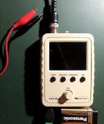
I will try to check for the ocsillation with the oscilograph as you propose (though I do not have a proper one, just a small handheld DSO Shell).
So far I have the following in my plans (by priority):
- listen to Zen Mod and install BC556 in place of JFETs as a test
- measure JFETs out of circuit to see what I get
- install 100ohm resistors instead of J1 and J2
- install 100ohm resistor in R30
- install the Hum Breaking Resistor (HBR) as proposed
- change all the ZTX450 and ZTX550
- change all the 0.47ohm resistors
- change the input wires (in other builds I just used simple unshielded twisted pair and they are fine, here I tried some shielded two wire cable)
And, I'm affraid, I have one other very nice option - change the AJ PCBs to the Zen modification PCBs that are on the way to me already with all the components waiting in the box 😀
Sorry if I sound stubborn or something but I do not feel easy to start re-soldering something without seeing and understanding some symptoms that would hint to some specific faulty part. Do I want too much? Perhaps that's something that not always happen in DIY world?
Now, I did not change the 0.47ohm resistors. They look pretty fine and on the right side they were never exposed to any high temperature even theoretically. And I measure nice and stable voltages of 0.398-0.402 accross them all.
As of JFETs, there is always a chance I could damage them while handling and soldering somehow (both sides though?). If that would be my first build, I would definitely be calling myself a wretched builder and would start resoldering everything immediatelly. But as all the other builds went smoothly without any troubles I do have (too much?) confidence in myself already 🙂
I will try to check for the ocsillation with the oscilograph as you propose (though I do not have a proper one, just a small handheld DSO Shell).
So far I have the following in my plans (by priority):
- listen to Zen Mod and install BC556 in place of JFETs as a test
- measure JFETs out of circuit to see what I get
- install 100ohm resistors instead of J1 and J2
- install 100ohm resistor in R30
- install the Hum Breaking Resistor (HBR) as proposed
- change all the ZTX450 and ZTX550
- change all the 0.47ohm resistors
- change the input wires (in other builds I just used simple unshielded twisted pair and they are fine, here I tried some shielded two wire cable)
And, I'm affraid, I have one other very nice option - change the AJ PCBs to the Zen modification PCBs that are on the way to me already with all the components waiting in the box 😀
Sorry if I sound stubborn or something but I do not feel easy to start re-soldering something without seeing and understanding some symptoms that would hint to some specific faulty part. Do I want too much? Perhaps that's something that not always happen in DIY world?
Attachments
Thanks for the great build guide & forum support!!
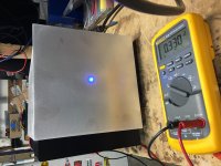
Got one mono heating up...bias & offset came right in. In few hours I’ll have a listen.
Then start the other channel.
Got one mono heating up...bias & offset came right in. In few hours I’ll have a listen.
Then start the other channel.
Attachments
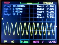
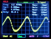
Me back again with some more o'scope pictured and video clips (yeh, I do realize I am a moron, as in Zen Mod's words cited by Monk55).
I tried to poke arround looking for the oscillation as advised by Boky. Put the probes on the R4 end connected to output and on the joint point of R11 and R12. Tried different frequencies on the generator, saw these frequencies on the scope, but nothing dramatic. Though it's difficult to tell what you see when you do not know what you are looking for. 😱
I attach some pictures and short video clips.
1) I see this on the power supply coming to the board. About 170mV of 100Hz modulated with some higher frequency.
2) At 10kHz I can see that the sine waves are not of the equal amplitude, about every second wave is a bit smaller/higher. Also the video attached shows the wobbling.
3) Similar wobbling can be seen on the 1kHz signal.
Does it tell anything, or is all this just the error margin of my toy DSO Shell osciloscope?
Attachments
The oscillatons will be quite high in frequency, try changing the time-base... while observing the sinewave. I am not sure what the time-base range is (max frequency) on that oscilloscope...
The 0.47ohm/3W resistors are not wire-wound, they are film resistors and as such, they may get damaged and not show that as an obvious discolouration... replace them all.
The JFET's.. try replacing them and then see what happens. As I said, they can still measure okay - but misfire in the circuit, unless you check their transconductance...
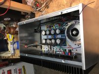
The toroid transformer is not mu-metal shielded, so that twisted pair used for LED can still feed the hum back to PCB.
If it was my amp, I would load it with capacitive loads until it starts oscillating... just a bit... this would tell me more about the possible root cause.
Or, write it off (use it as a testbed) and build a new Aleph J / new SS Aleph J.
Check with Zen Mod about this: "So far I have the following in my plans (by priority): Zen Mod and install BC556 in place of JFETs as a test"; those BJT's need a correct base biasing... I do not think they will work if you just plug them in.
The 0.47ohm/3W resistors are not wire-wound, they are film resistors and as such, they may get damaged and not show that as an obvious discolouration... replace them all.
The JFET's.. try replacing them and then see what happens. As I said, they can still measure okay - but misfire in the circuit, unless you check their transconductance...
The toroid transformer is not mu-metal shielded, so that twisted pair used for LED can still feed the hum back to PCB.
If it was my amp, I would load it with capacitive loads until it starts oscillating... just a bit... this would tell me more about the possible root cause.
Or, write it off (use it as a testbed) and build a new Aleph J / new SS Aleph J.
Check with Zen Mod about this: "So far I have the following in my plans (by priority): Zen Mod and install BC556 in place of JFETs as a test"; those BJT's need a correct base biasing... I do not think they will work if you just plug them in.
Last edited:
I can not tell if you wired inputs as RCA's, or XLR's...
XLR (balanced topology) and Aleph J go together like a baby bum and the potty. You will not need any ground-lift resistors. My Aleph J is absolutely, totally dead-quiet. Zero hum/buzz. Beautiful!
XLR (balanced topology) and Aleph J go together like a baby bum and the potty. You will not need any ground-lift resistors. My Aleph J is absolutely, totally dead-quiet. Zero hum/buzz. Beautiful!


Beautiful indeed!
I see that J1 and J2 do not face each other in this version. So there's no need for them to keep each other in a warm hug. Right?
I see that J1 and J2 do not face each other in this version. So there's no need for them to keep each other in a warm hug. Right?
Wrong.
You want them to thermally track each other to keep the Ic through both the same in all conditions.
You want them to thermally track each other to keep the Ic through both the same in all conditions.
Well, that's what I'm asking. Why then J1 and J2 do not face each other on this Zen version PCB. Is this an overlooking in design, or was it decided that it's not so important?


Well, that's what I'm asking. Why then J1 and J2 do not face each other on this Zen version PCB. Is this an overlooking in design, or was it decided that it's not so important?
Yes, give naughty boy Choky a hiding. Or send him to corner for year.
😀
Last edited by a moderator:
I have recently re-wired the speakers' return (negative) to go straight to the power supply PCB common with a major improvement in both distortions reading and in perceived sound quality; quite amazing actually. However, most of the (all??) amps I see here have speakers' return going to the amp PCB's, and then to the PS common. This seemed wrong to me when I built the amp... but I was so busy with work that I did not really have time to do this wiring correctly.
I had some spare time recently and managed to get this done right (finally). In general, the current flow should be from + and - power supply rails (capacitors' bank), through the MOSFETS, down to the speakers positive, and then back, straight to the closest point possible between the large power supply reservoir capacitors (or the secondary winding' common, with the centre-taped transformers). With DIY store's power supply PCB, the lugs closest to the capacitors should go to the speakers; the lugs further from the capacitors should go to the amp PCB common.
I had some spare time recently and managed to get this done right (finally). In general, the current flow should be from + and - power supply rails (capacitors' bank), through the MOSFETS, down to the speakers positive, and then back, straight to the closest point possible between the large power supply reservoir capacitors (or the secondary winding' common, with the centre-taped transformers). With DIY store's power supply PCB, the lugs closest to the capacitors should go to the speakers; the lugs further from the capacitors should go to the amp PCB common.
Last edited:
Boky, could you please share your noise and distortion measurements? It would be nice to see the levels of the power supply hum/buzz you get and the levels of harmonics.
- Home
- Amplifiers
- Pass Labs
- Aleph J illustrated build guide