Yes. The center is the signal, the shield is ground. (Return)
The VGA cables are probably perfect!
I have been using cable scraps for hook-up wire for so long I can't remember the last time I actually purchased wire.
Sure, but where do you purchase your color matched cable ties?
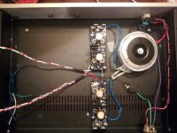
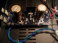
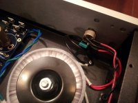
 Well, I started up the BA-3...actually just the power supply.
 Immediately popped a 2A fast blow fuse. Damn it.
while I am assembling a bulb tester you guys have any ideas?
Here's whats going on:
- From the power inlet Red is Live, black is N.
- Antek transformer, Primary has two leads for power. Red and Red/ black and black tied to each other (i.e. red + red = live, black + black = N) after the power switch.
- Purple wire is transformer "static shield" that should be grounded.
- Secondaries to the PSU boards. Each set of secondaries (green and blue) measure infinate resistance between them.
- Cap on the output of the power switch (Y rated)
- Doesn't matter which secondaries go to the diode bridge right? It's AC so I think it doesn't matter. It's not like the A/C connections on the diode board are specific, right?
- Leads from the PSU (red/White/Green) are not connected to anything yet.
- I briefly measured about 5V on the PSU before I realized the fuse was blown.
Could this just be the the startup load that blew the fuse? I have 1A slow-blow fuses I will use but I thought I'd start it with a fast blow to be safe.
Last edited:
Purple wire is transformer "static shield" that should be grounded.
Attach that wire to screw where the thermistor is attached, not AC earth. It's a subtle change, but still worth doing. (That's not causing the fuses to blow, however)
Yes and no, make sure the blue/green are attached to the same places on each bridgeDoesn't matter which secondaries go to the diode bridge right? It's AC so I think it doesn't matter. It's not like the A/C connections on the diode board are specific, right?
Take all that off, including the tied grounds and see if each individual PCB is working properly.- Leads from the PSU (red/White/Green) are not connected to anything yet.
Try the slow, but I doubt that those PSU caps should pop a 2A fast...Could this just be the the startup load that blew the fuse? I have 1A slow-blow fuses I will use but I thought I'd start it with a fast blow to be safe.
vdi_nenna said:Is a thermistor necessary is this application?
Can't hurt, and will probably help the overall noise floor.
Last edited:
I'll look at the A/C connection from the transformer to the diode board. I am not sure if each board is hooked up the same way. I thought it didn't matter.
6L6, good idea to test each board independently…I'll try that.
Vienna, the thermistor is just a ground loop breaker/isolator. Maybe I should leave it out when testing. Maybe it's safer that way.
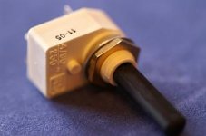
Also I should not that when switched on there was quite a spark/arc inside the power switch. It has a transparent window on the back of the switch and there was some arcing when switched on. Is this normal?
DPST. Here's the specs:
----------------------------------------
RS-4A
A DPST switch with a glass-loaded flame retardant body and spindle, and silver contacts.
Capable of withstanding inrush current of 64A for 10ms.
Contact rating 250VAC 4A
Angle of rotation 45°
Made in UK
Weight :12 (gram/each)
----------------------------------------
RS-4A
A DPST switch with a glass-loaded flame retardant body and spindle, and silver contacts.
Capable of withstanding inrush current of 64A for 10ms.
Contact rating 250VAC 4A
Angle of rotation 45°
Made in UK
Weight :12 (gram/each)
Attachments
The 317/337 can do +/- 25V -- the regulator I am using is exactily that.
You need to change a resistor value or two in order to get that voltage. Easy enough to figure out, or just ask for a hand.
The most important thing, however, is the voltage rating of your capacitors - look at your reg and see what they are. If they are 25V or better, you are good to go, if not you probably need to swap a few new ones in.
My QC guy testing Front-end
Passed!
PSU wiring. Sometimes I think the only trick to making this stuff look fairly good is the copious use of zipties...
Vince - this photo is for you - it shows the PCB connections, I will get a shot of the attenuator as well. You can do it with no changes to the PCB.
I realise this is a bit of a teaser, but more photos later. The short story is that it works, biases properly, is very quiet, and sounds as good as I've been imagining!
I will also measure and illustrate the effects of changes to P3.
Until then,
Happy Thanksgiving everybody!
- Home
- Amplifiers
- Pass Labs
- BA-3 As Preamp
