John,
The LD1085 has a 30V max limit I think. 22V rectified to DC might put you over 30V. A 20V transformer will get you 28ish volts. Better I think, but hard to find a 20V transformer.
I went with LM317/337 because really it seems like thats the only choice if you want more than 25V after regulation. Unless you go discrete or shunt or something. I may build a salas shunt regulator after I get it up and running. I am shooting for 30V rails.
Go with the 20K attenuator. If I remember right, he glassware attenuators only have like 16 steps. If your volume needs are specific (listen late at night w/people sleeping, live in an apartment, etc.) and require a lot of fine adjustment it may not be enough steps. I use a 24 step attenuator now and sometimes wish for an in-between setting late at night when the family is asleep.
Perhaps!
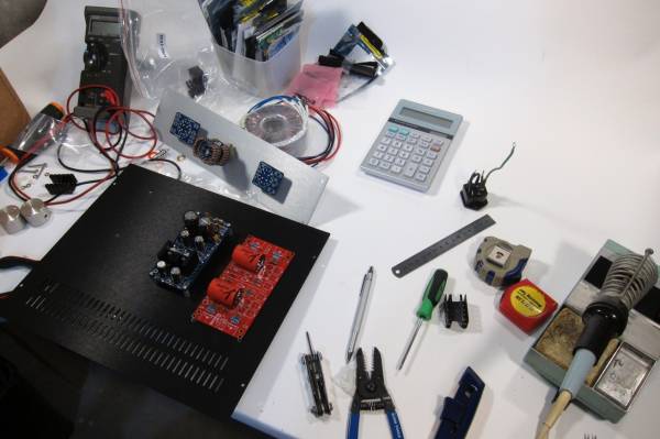
But I don't have the boards completely stuffed so I need to make another Digi-Key or Mouser order...
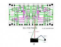
A bit of advice - the pot will take the place of R2 on the PCB, input to the junction of R1/R2, output to the Jfet Gates and then connect the pot to ground. A little surgery or creative thinking will be needed for those connections. Nelson has suggested keeping R1, as it's there to stop parasitic oscillation.
But I don't have the boards completely stuffed so I need to make another Digi-Key or Mouser order...
A bit of advice - the pot will take the place of R2 on the PCB, input to the junction of R1/R2, output to the Jfet Gates and then connect the pot to ground. A little surgery or creative thinking will be needed for those connections. Nelson has suggested keeping R1, as it's there to stop parasitic oscillation.
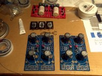
The beginnings of a BA-3 preamp.")
subscribed...
This might be a race to see who gets done first.
I'm on your heels.
Attachments
A bit of advice - the pot will take the place of R2 on the PCB, input to the junction of R1/R2, output to the Jfet Gates and then connect the pot to ground. A little surgery or creative thinking will be needed for those connections. Nelson has suggested keeping R1, as it's there to stop parasitic oscillation.
Wouldnt just removing R2 and putting the pot in front of R1 work?
vdi:
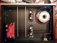
What are you using for regulators? LM317/337? Why two boards? Dual mono?
Also, anybody know how to "zero" p1 and P2 before startup? Just measure across + and - of the elecrolytics (c1 & c2) until they read 0 ohms?
Also, here comes the stupid questions, any good advice to where to set P3 to a "middle" value? Can I measure across r3 or r4 (10 ohm resistors) while turning the pot to set each channel evenly? Should I look for 5 ohms? Trim pots, caps and jpgs are already in.
Wouldnt just removing R2 and putting the pot in front of R1 work?
don't know, but you may need a coupling cap between pot/att and preamp input
What are you using for regulators? LM317/337? Why two boards? Dual mono?
LT1085 and 1033. Dual-mono only to the rectifiers. Only one transformer.
don't know, but you may need a coupling cap between pot/att and preamp input
I've looked at several low level circuits and caps on the input are predominately used in circuits with non-symmetrical power supplies, except the J-BoZ.
The circuit input that most closely resembles the B3-Pre (that i could find) is the B1 buffer. It uses cap because its power supply is single ended.
Whatever Mr Pass told 6L6 must have been to get the best out of the circuit, but I need clarification.
The circuit input that most closely resembles the B3-Pre (that i could find) is the B1 buffer.
The B1 resembles the BA-3 in that Nelson designed it, and it uses some similar parts... But other than that...
The closest circuit is actually the F5. It, like the BA-3 FE, has no input cap.
It uses cap because its power supply is single ended.
sorry, yes, I was probably thinking of single ended when suggesting input cap
The B1 resembles the BA-3 in that Nelson designed it, and it uses some similar parts... But other than that...
The closest circuit is actually the F5. It, like the BA-3 FE, has no input cap.
That's not the point, what you proposed earlier still doesn't make sense.
I am confused about the volume pot wiring. I was just going to do this an omit R2.
Is this wrong?
What happens with the input at R1? This the whole confusing conundrum.
R1 has to be before the jfets to prevent oscillation. In order for R1 to help prevent oscillation, R1 has to be in the signal path.
I'm just going to put the pot in front of R1, unless someone can give me a better reason not to.
Its not going to blow up, it will either work, not work, sound good or just sound like crap.
Last edited:
Is this wrong?
What you show omits R1 as well... Now that I'm looking it at I wonder is there is a way to keep R1 on the PCB without a bunch of extra wires, where if you just put it in line with the input hot, then it will work as drawn.
I asked Nelson if R1 was necessary in my case as I will be using a stepped attenuator - he replied it was. It's there to keep HF junk from causing oscillation. (A possible side-effect of such a wide-bandwidth machine.)
vdi_nenna said:That's not the point, what you proposed earlier still doesn't make sense.
What did I propose? I'm not sure what you are referencing...
- Home
- Amplifiers
- Pass Labs
- BA-3 As Preamp