You probably understand it better than I, I was just asking
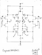
buzzforb. Mr. Pass writes clearly; to educate and inform. I look for connections and analogies. I hope the attached simplified image of the circuit will keep you enthralled in the SUSY thing. With ZV6 article in mind:
- The output stage shows 2 conjoined complementary symmetry diy or clone SOX [R].
- I added a feeback resistor Rf from the gate to the drain of each output MOSFET like in ZV6.
- If I am theoretically on track, then the harmonic distortion at the outputs [arrows] point in the same direction. This means their amplitudes are equal and their phases are aligned in the same direction.
- The preamp output signals will go through a balanced power amp. The arrows [from preamp] will still be aligned as shown for cancellation across the loudspeaker.
Attachments
One disadvantage that I see is that the input pair is not included in the error current loop, so you do not get any corrective help with them. Do you agree?
I agree.One disadvantage that I see is that the input pair is not included in the error current loop, so you do not get any corrective help with them. Do you agree?
If you were to use the BA-3 circuit as a stand-alone preamp, and out a 50K put in front of it, what would you do with R1 and R2?
R1 is there to stop oscillations, so keeping it seems like a good idea.
R2 is for a ground reference on the input and set the input impedance, so could you just replace it with the pot for volume control?
R1 is there to stop oscillations, so keeping it seems like a good idea.
R2 is for a ground reference on the input and set the input impedance, so could you just replace it with the pot for volume control?
oops
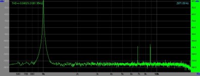
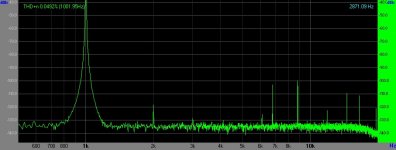
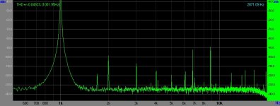
1- Soundcard 1V Loopback
2- Soundcard 1V - Amp 3.2V output
3- Soundcard 2V Loopback
4- Soundcard 2V - Amp 6.47V output
5- Soundcard 3V Loopback
6- Soundcard 3V - Amp 9.83V output
Higher harmonics are present in test setup, so it is hard to know what it amp and what is setup. If not for them, it looks good to me.
Attachments
-
 Soundcard 1V loopback-bmp.jpg57.3 KB · Views: 922
 -
 Soundcard 1V - Amp 3-3V output-bmp.jpg58.7 KB · Views: 883
 -
 Soundcard 2V loopback-bmp.jpg58.3 KB · Views: 870
 -
 Soundcard 2V loopback - Amp 6-4V output-.jpg60.1 KB · Views: 727
 -
 Soundcard 3V loopback-bmp.jpg58.5 KB · Views: 180
 -
 Soundcard 3V - Amp 9-8V output-bmp.jpg61.7 KB · Views: 199
Last edited:
Nice Buzz.
If building the BA-3 standalone would it be better to go with a regulated power supply?
The BA-3 when used w/the burning amp power sections is just fed from the unregulated power amp supply, right?
I am thinking of doing a BA-3 w/ f5-style PSU with a w/100va transformer and 8x1,200uf caps (about 5K per rail). But I'd go regulated if you guys who are smarter than me seem to think it's worthwhile.
I would use a regulator. Can only improve overall performance. This wa plugged into simple linear reg from Pass balanced line stage article.
I've never built anything w/a regulated PSU. Well, with the exception of SMPS supplies.
I've been doing a little research and I am starting to understand the merits of discrete vs IC based regulation. I think I' like to go discrete.
I've seen the Pass Balanced Line Stage PSU schematic...seems good but I'd like use a PCB.
What's your guys' thoughts on this:
The σ22 Regulated Power Supply
It's discrete, pretty close to the Pass PSU in design and PCB's are available.
Or any other reco's appreciated (Shunt, Kubota, etc.).
Thanks.
Contact Peter Daniel for his universal power supply boards. $20 each.
You can drop in 79xx/78xx, Linear Technologies 1033/1085 or LM377/317 regulators. Adjustable Semiconductor Regulators
Or, build Salas' shunt regulator.
I'm using Peter's board with LT 1033/85.
You can drop in 79xx/78xx, Linear Technologies 1033/1085 or LM377/317 regulators. Adjustable Semiconductor Regulators
Or, build Salas' shunt regulator.
I'm using Peter's board with LT 1033/85.
OK, BA-3 pcb ordered.
I plan on use this LT1085/LD1085 regulator at 24V:
New bipolar low-voltage power supply for solid-state projects
Here come the newbie questions, I've never built a preamp power supply:
What voltage transformer should I use...I suppose the regulator drops about 10V (I am guessing) so maybe a 32V transformer? What VA rating is wise for this application? 100VA?
Also, is it wise to separate the PSU ground from the chassis ground w/a thermistor or something a la the standard Pass power amp wiring?
Also, I am going to use the fairchild mosfets instead of the Toshibas becasue well, I can get them cheaply and easily. I have a stash of PRP resistors I will use and matched 170/174 Jfets.
Also, I have a pair of 8.2uf clarity caps I's like to use. The output cap spec is 10uf, what will happen if I use 8.2 instead?
The BA-3 will push an F5. Currently I am using a jfet BOZ on batteries which actually sounds quite good. I am hoping the BA-3 is better. Much better. Anybody have any first hand experience w/a BA-3 in front of an F5 let me know.
Thanks.
What voltage transformer should I use...
Voltage of secondary only needs to be a few volts over the required voltage.
Take the voltage output of the transformer and multiply it by 1.414. 22v x 1.414=31.108v.
Also, is it wise to separate the PSU ground from the chassis ground w/a thermistor or something a la the standard Pass power amp wiring?
I don't think it's necessary, but it can't hurt. Maybe there's a question of how much current will flow through the thermistor.
Also, I am going to use the fairchild mosfets instead of the Toshibas becasue well, I can get them cheaply and easily
Just be sure the spec are as good or better in capacity.
Also, I have a pair of 8.2uf clarity caps I's like to use. The output cap spec is 10uf, what will happen if I use 8.2 instead?
Maybe less bass performance, but probably not. By-pass it with a good quality cap to get closer to 10uF and better performance.
The BA-3 will push an F5. Currently I am using a jfet BOZ on batteries which actually sounds quite good. I am hoping the BA-3 is better. Much better. Anybody have any first hand experience w/a BA-3 in front of an F5 let me know.
I personally haven't finished it yet.
OK, BA-3 pcb ordered.
I plan on use this LT1085/LD1085 regulator at 24V:
New bipolar low-voltage power supply for solid-state projects
His PCB are really nice. However, if he only has 25V caps supplied, that's going to be tight on the output side, and much too low on the input. He mentions that the acceptable upper output voltage is 22V. However, that seems to be based on cap rating, so you can always change them.
What voltage transformer should I use...I suppose the regulator drops about 10V (I am guessing) so maybe a 32V transformer? What VA rating is wise for this application? 100VA?
First, the dropout of the regulator will be nothing close to 10V, and if you need to throw away that much, all you are dong is making heat.
Plan on 3-5V dropout. (and it will likely be less, but 5 is an easy number)
If you want 24 out, you need 29 in.
22V x 1.4= 30.8
-1.4 for the diodes, = 29.4. Perfect.
And that's assuming 5 volts of dropout through the regulator, it will actually be less.
So a 22+22V transformer will be fine. 50-100VA, it won't use but a fraction of it, but small transformers have less regulation, making the regulator circuit work harder.
Also, is it wise to separate the PSU ground from the chassis ground w/a thermistor or something a la the standard Pass power amp wiring?
Yes, or a 5ohm 10W resistor, or a couple of diodes and a cap, there is lots of information in Broskie's guide.
Also, I have a pair of 8.2uf clarity caps I's like to use. The output cap spec is 10uf, what will happen if I use 8.2 instead?
The LF rolloff increases a teeny bit, from about 3Hz to 5Hz. That's so low it doesn't matter. Use the 8.2uF and don't worry. 🙂
Anybody have any first hand experience w/a BA-3 in front of an F5 let me know.
Actually, I'm looking forward to hearing your impressions!
I didnt think about the cap rating. Good catch.
Damn, I like Broskie's board and the IC's can go to 30V. But replacing the caps w/35V adds to the costs.
Anybody know of a good regulator kit for this application? Maybe this?
Kubota Low Noise Regulator Full Blown Version Kit | eBay
Damn, I like Broskie's board and the IC's can go to 30V. But replacing the caps w/35V adds to the costs.
Anybody know of a good regulator kit for this application? Maybe this?
Kubota Low Noise Regulator Full Blown Version Kit | eBay
Your link is dead.
Look at this from AMB, it's discrete and pretty cool.
The σ22 Regulated Power Supply
Somebody mentioned earlier the Peter Daniel PCB, it has the ability to do exactly what you are after, with a 317/337 or 7824/7924. There is room for lots of capacitance, high-speed diodes, etc... It's a really cool board.
Sorry, here's the link:
Kubota Low Noise Regulator Full Blown Version Kit | eBay
I checked out the AMB board. Looks actually like the best option. But I did the math and it would be over $100 to build. That's a little out of my comfort zone.
I lloked for Peter Daniel's board but I couldn't find it on his site.
Kubota Low Noise Regulator Full Blown Version Kit | eBay
I checked out the AMB board. Looks actually like the best option. But I did the math and it would be over $100 to build. That's a little out of my comfort zone.
I lloked for Peter Daniel's board but I couldn't find it on his site.
It's not on his site, look at this thread -
http://www.diyaudio.com/forums/audio-sector/149672-universal-power-supply-pcb.html
http://www.diyaudio.com/forums/audio-sector/149672-universal-power-supply-pcb.html
- Home
- Amplifiers
- Pass Labs
- BA-3 As Preamp