Hey Osscar,
On the amps you built with the MJ11015/16 did you try to match the output transistors? If not have you measured across Re to see how well matched they are? Just wondering if a guy can get away with out matching and using .2-.5 Re.
On the amps you built with the MJ11015/16 did you try to match the output transistors? If not have you measured across Re to see how well matched they are? Just wondering if a guy can get away with out matching and using .2-.5 Re.
You may also consider the 2SB1383 / 2SD2083... They are TO-3P devices, Ic of 25A, min. hFE around 2000 and good low Cob numbers to parallel outputs.So I'm already thinking about the next version. I would like to push this design to around 300W/chan. I would attempt this by raising voltage to 52-56 rails. I would change outputs to T-03 package MJ11015/6 or the same ones in the A40 if available. My question would be does anyone see issues with connecting outputs with short wires from the board to trannies? The A40 is built that way actually output wires are not that short and the 40 doesn't call out base stopper resistors. Match some outputs and lower Re to around .3 Ohm
One thing to keep in mind, the 2SB1383 is very fast (fT = 50MHz), the 2SD2083, fT =20MHz, but they are cheaper than MJ11015/6
Digikey still carries them:
https://www.digikey.com/product-detail/en/sanken/2SB1383/2SB1383-ND/3929429
2SD2083 Sanken | Discrete Semiconductor Products | DigiKey
One type of transformer is that in first pic?
i think it's an EI type transformer - only the core has different design - dual core. It is a salvaged transformer from old PA amplifier. Green one is c core with two separate windings - by theory, it is possible to connect windings so that it has a smaller radiated field.
Hey Osscar,
On the amps you built with the MJ11015/16 did you try to match the output transistors? If not have you measured across Re to see how well matched they are? Just wondering if a guy can get away with out matching and using .2-.5 Re.
no i didn't - because when measuring the individual transistor's DC current on its individual RE - they are pretty accurate - a difference of a few mV only. maybe I was lucky, but they seem to be pretty close to each other from the factory.
You may also consider the 2SB1383 / 2SD2083... They are TO-3P devices, Ic of 25A, min. hFE around 2000 and good low Cob numbers to parallel outputs.
One thing to keep in mind, the 2SB1383 is very fast (fT = 50MHz), the 2SD2083, fT =20MHz, but they are cheaper than MJ11015/6
Digikey still carries them:
2SB1383 Sanken | Discrete Semiconductor Products | DigiKey
2SD2083 Sanken | Discrete Semiconductor Products | DigiKey
MJ 110115/16 and tip 142/147 they have lower built-in resistor values ( 40 R),...these Japanese darlingtons have 80R ...and original lambda PMD - has 25R...As NP once said - those with the lowest resistance work more in Class A region as driver transistor.
Has anyone build this amp using PCB by Mr. Pass?
I have found some discrepancy between PCB and schematic.
In schematic collector of q2 connects directly to v+ via r16.
In PCB however, this collector terminal connects to r6 r7 and emitter of q6.
Any thought? Mistake or a modification?
Thank
C.S.
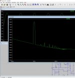
I do a little simulation:
original connection looks a bit better (2 & 3 H) - but total thd seems to be better on "alternative" connection - 0,021 vs 0,02 ( its seems little underbiased with 20mA per transistor with 0,5R in my sim with 20mA per transistor- with 0,5R its better to rise bias to 30mA per transistor - THD and harmonics will be reduced to the same level like 1R and 20mA )
Attachments

Last edited:
I am wondering if anyone who successfully build this amp could share his BOM with me? I know "it is DIY", "read the whole thread"...but I am beginner I would like to avoid beginners mistakes🙂
Thanks in advance!
P.S.
I just ordered 10 PCB (Nelson's design) and may have couple of pairs for sell - shipment from Germany. Cost would be on the original cost level - TBD when they will arrive.
Thanks in advance!
P.S.
I just ordered 10 PCB (Nelson's design) and may have couple of pairs for sell - shipment from Germany. Cost would be on the original cost level - TBD when they will arrive.
Hi xbitwise. Here is my BOM for the AB100. Most of the parts are sourced through Mouser. This is just a guide since I have some of the parts in my "inventory" already and there are also a few substitution parts here and there. Let us all know if you have any questions though. Good luck with your build!
Attachments
Hi jwjarch,
Thanks a lot! In this moment still waiting for PCBs but should start building next week.
Thanks a lot! In this moment still waiting for PCBs but should start building next week.
Hi xbitwise. Here is my BOM for the AB100. Most of the parts are sourced through Mouser. This is just a guide since I have some of the parts in my "inventory" already and there are also a few substitution parts here and there. Let us all know if you have any questions though. Good luck with your build!
hi, do you have a pair of pcb x me? thanksI am wondering if anyone who successfully build this amp could share his BOM with me? I know "it is DIY", "read the whole thread"...but I am beginner I would like to avoid beginners mistakes🙂
Thanks in advance!
P.S.
I just ordered 10 PCB (Nelson's design) and may have couple of pairs for sell - shipment from Germany. Cost would be on the original cost level - TBD when they will arrive.
hi, do you have a pair of pcb x me? thanks
Actually yes, I just received them today. Please PM me.
Maybe these can be tried instead of the original Japanese for VAS?
deg 2sa1110 Japan Transistor PNP 120 V 500 MA 4,5 W deg | eBay
2sc2590 Japan Transistor NPN 120v 500ma 5,0w | eBay
I have tried various "isc" transistors in hiraga le monstre amplifier - worked without any problems.. my bad that I didn't find these when I built my AB100- I'm too lazy to change them now.
So I have this amp built and have used it for a few weeks now. Does anyone see a problem with having the power transformer connected through about 3' of 12 gauge wire? It is supplied by a 3kVA trannie. Just AC to two separate bridges mounted close to each main board.
So I have this amp built and have used it for a few weeks now. Does anyone see a problem with having the power transformer connected through about 3' of 12 gauge wire? It is supplied by a 3kVA trannie. Just AC to two separate bridges mounted close to each main board.
Hi Freecrowder, I don't see any problem here. I don't know your amp configuration, but at 8 ohms load, you probably will see a max of 10 amps for stereo. With the nominal resistance of 12 gauge wires at 1.6 mOhms/feet (per Wikipedia), then you see a 50mV drop across the line. This is nothing.
Congrats on finally completing your amp
 , I still have to build mine.
Can this amp be "converted" to a A100 by adjusting the bias to let's say 3A ?
It could be interesting to see the distortion profile between the two to see if we by measurement could see a "sound difference"?
It could be interesting to see the distortion profile between the two to see if we by measurement could see a "sound difference"?
i have simulated AB 100 with some 20-24V rails @ 2-3A - the harmonic spectrum is dominated by 3H .. 2H is not practically visible and the highest harmonics are also absent. But heat dissipation will be 120W approx, and maybe no need for 4 pairs of darlingtons. But I think this amplifier is designed for other purposes - more power at less cost and it should sound good.
Ok.....3H dominant would be expected if PP stages are in perfect balance.
What I am after is if it is possible to see by measurement when PP output stage transistors switches on and off compared to class A where they are always on.
Also it could be interesting to see artifacts from NFB vs. an amp without NFB. This would be at high frequencies I assume?
There is a lot of theory about it but interesting to watch it in real measurements.
Can this amp be "converted" to a A100 by adjusting the bias to let's say 3A ?
Just a turn of the pot away....

The heatsinks in a 5U Deluxe may be able to handle it. +-50V and 3A …..300W pr. channel. It may be a bit too much…...even for a 5U Deluxe. If built as mono blocks using 5U Deluxe it will be difficult to utilize heatsinks in both sides I guess…..
Hello Mr. Pass!
Thanks for posting this amp.
I see a simple design, cheap and with very good characteristics for its cost!
Now I am making a similar amp one with the same darlington transistors, you put 4 pair of power transistors, It's possible excess?, but I wonder the following:
In my desing with just one pair of npn / pnp power transistors, would the SOA area be correct to power supply of 2x28vac (+ -39vdc) and obtain powers of 70W at 8 ohm and 100W at 4 ohm?
Or do you think I will need to turn down level voltage the power supply to use only one pair of power transistors?
At what voltage would you recommend the power supply for only one pair of power transistors for use the amplifier also at 4 ohm impedances?
Thank you!
Last edited:
- Home
- Amplifiers
- Pass Labs
- AB100 Class AB Power Amplifier