Yeah I wasn't aware of that site. Compare a bunch of makers. I had to pay extra on mine for 1.6mm thickness.
I distinctly remember back when a modest prototype board cost $1000 and
took a month. And that was back when the dollar was still worth a quarter.
These days it's maybe $50 and as long as a week, but usually 4-5 days.
It's a fine time to be a DIYer.

took a month. And that was back when the dollar was still worth a quarter.
These days it's maybe $50 and as long as a week, but usually 4-5 days.
It's a fine time to be a DIYer.
Along with the research capability of the internet, is like never before!I distinctly remember back when a modest prototype board cost $1000 and
took a month. And that was back when the dollar was still worth a quarter.
These days it's maybe $50 and as long as a week, but usually 4-5 days.
It's a fine time to be a DIYer.
I remember having to spend many hours on the phone trying to get through to engineers in various industries, trying to find parts and information.
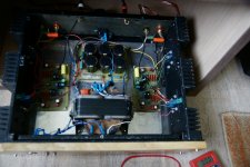
Well I've been listening to this amp for a cd's worth of music now. WOW very impressed. This thing is holographic. The first thing that it's sticking out is fantastic imaging! Maggie IIc's, Aikido Pre and Cambridge CD player. The amp is running on temp transformer. It is a 2kVA trannie so plenty stout. Dual bridges. 45 vdc rails. I have been running a HB for about 2 years now and an A40 before that. Dead quite when silent. Very Very good so far. I see a lot of people fretting over the fact that it is an AB. i'm not.
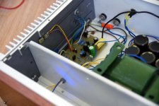
Only now I saw that you finally completed both channels -Congratulations!
I agree about the sound - very detailed and "3d sound" and very good bass.
I agree about the sound - very detailed and "3d sound" and very good bass.
Has anyone build this amp using PCB by Mr. Pass?
I have found some discrepancy between PCB and schematic.
In schematic collector of q2 connects directly to v+ via r16.
In PCB however, this collector terminal connects to r6 r7 and emitter of q6.
Any thought? Mistake or a modification?
Thank
C.S.
I have found some discrepancy between PCB and schematic.
In schematic collector of q2 connects directly to v+ via r16.
In PCB however, this collector terminal connects to r6 r7 and emitter of q6.
Any thought? Mistake or a modification?
Thank
C.S.
Same here.Mine are from Pass gerbers. Seems to work just fine so far.
Also harvest output from both differential input transistors to reduce distortion. Similar to the technique used on what Erno Borbely called "Lender True Symmetry".Mine are from Pass gerbers. Seems to work just fine so far.
Well I've been listening to this amp for a cd's worth of music now. WOW very impressed. This thing is holographic. The first thing that it's sticking out is fantastic imaging! Maggie IIc's, Aikido Pre and Cambridge CD player. The amp is running on temp transformer. It is a 2kVA trannie so plenty stout. Dual bridges. 45 vdc rails. I have been running a HB for about 2 years now and an A40 before that. Dead quite when silent. Very Very good so far. I see a lot of people fretting over the fact that it is an AB. i'm not.
Freecrowder - Did you build the boards using the values from the schematic, or did you change anything? I'm especially interested in the 100uF input capacitor and the 1 ohm emitter resistors on the outputs.
Freecrowder, I’m interested in RickRay’s post and what VAS transistors did you end up going with in place of the 2SA1110 and 2SC2590?
For the VAS transistors I used the MJE340/350. Emitter resistors I used .68ohm 3 Watt. The coupling cap is a nichicon audio rated electrolytic. The newer Nichis and Panasonic audio graded electrolytic sound just find from everything I'm hearing.
So I'm already thinking about the next version. I would like to push this design to around 300W/chan. I would attempt this by raising voltage to 52-56 rails. I would change outputs to T-03 package MJ11015/6 or the same ones in the A40 if available. My question would be does anyone see issues with connecting outputs with short wires from the board to trannies? The A40 is built that way actually output wires are not that short and the 40 doesn't call out base stopper resistors. Match some outputs and lower Re to around .3 Ohm
No problem with the To-3 transistors and their wires IMHO - I put the 100R base stopper directly on the base pin and 100R on the PCB. But I think we could do without it. In my amps (Mj11015 / 16) one has 0.5R (two 1R parallel) RE resistors and the other has 0.23R (two 0,47R parallel).
Attachments
- Home
- Amplifiers
- Pass Labs
- AB100 Class AB Power Amplifier