Hi
I also successfully built a stereo ACA 1.6, it works flawlessy:
- high quality parts
- reasonable price
- build description is very good
- if you need help, this forum will provide that to you
- the sound quality is very good
In the end, I just cannot understand why someone will buy a "fake" ACA kit with questionable quality, when you can get the real thing for a very reasonable price.
Thanks a lot
Alf from Norway
Thanks for the reply Alan4411
When I first assembled the ACA, it worked perfectly, other than the expected on/off pops. I added the delay/speaker protect to silence these pops. Since then I've had the issues, so during the upgrade process I've messed something up.
I have tested the ACA in the original configuration, i.e. with the speaker protect fully disconnected and the ACA connected directly to the binding posts. It still has the problem.
Yes, DC measures correctly on both amp boards. Bias is stable at 10V on both boards (within 0.1V). The 10V number comes from the build guide. Is 12V also an option? Tradeoffs?
This is the speaker protect I've got in the case: UPC1237 Speaker Protection Board DIY KIT Used Japan OMRON Relay for Dual Channel | eBay
Though even with it completely disconnected, the amp has the issue present.
I'll try get photos up shortly.
Not sure I quite understand the problem, but when you first installed the delay circuit, did the ACA function correctly? Or has it not worked properly since you installed the delay circuit?
When I first assembled the ACA, it worked perfectly, other than the expected on/off pops. I added the delay/speaker protect to silence these pops. Since then I've had the issues, so during the upgrade process I've messed something up.
Next as they both have the same 'fault' it is more likely a connection problem. Have you tried going back to the build guide configuration, with no delay circuit at all?
I have tested the ACA in the original configuration, i.e. with the speaker protect fully disconnected and the ACA connected directly to the binding posts. It still has the problem.
I assume you have measured +24 volts on the V+ connection on both boards and the 'bias' is still about +12 volts on both?
Yes, DC measures correctly on both amp boards. Bias is stable at 10V on both boards (within 0.1V). The 10V number comes from the build guide. Is 12V also an option? Tradeoffs?
Then, please post some good clear pictures, so we can see the wiring and show us what type of 'delay' you used.
This is the speaker protect I've got in the case: UPC1237 Speaker Protection Board DIY KIT Used Japan OMRON Relay for Dual Channel | eBay
Though even with it completely disconnected, the amp has the issue present.
I'll try get photos up shortly.
I have to fully adhere to all that has been pointed out by Variac, Jason and 6L6 about unscrupulous sites trying to make a profit from Mr. Pass's designs and DIYAudio equipment.... In the end, I just cannot understand why someone will buy a "fake" ACA kit with questionable quality, when you can get the real thing for a very reasonable price...
But, furthermore, this was my first question: how much 'cheaper' could it be when the store sells it for $129? My only possible answer has to do with availability... but this is not a life threatening scenario where anyone could not wait a couple of months for it... so yeah, no reason whatsoever to pick the counterfeits over the real thing, for all of the reason above posted.
People reporting these symptoms in the past (mudded and distorted sound with low volume and crosstalk between both channels) usually have a grounding issue. Perhaps when dissoldering or reconnecting things something in the inputs got shorted to ground? Or the mosfets got shorted to the heatsinks?...I have tested the ACA in the original configuration, i.e. with the speaker protect fully disconnected and the ACA connected directly to the binding posts. It still has the problem.
I'd start with the inputs, make sure that they are grounded correctly and that the hot ins are not shorted to ground and / or chassis.
Good luck!
Rafa.
... I have tested the ACA in the original configuration, i.e. with the speaker protect fully disconnected and the ACA connected directly to the binding posts. It still has the problem.
Yes, DC measures correctly on both amp boards. Bias is stable at 10V on both boards (within 0.1V). The 10V number comes from the build guide. Is 12V also an option? Tradeoffs?
This is the speaker protect I've got in the case: UPC1237 Speaker Protection Board DIY KIT Used Japan OMRON Relay for Dual Channel | eBay
Ok until we can see the pictures, best guess is you have swapped the 2 output wires round? The Red speaker connector is connected to the 0 volt line. The Black connector is the 'output'.
With your meter set to the 20k ohms range, measure the resistance from the red to the black speaker terminals. If correct it should be about 1k ohms.
Which ACA kit do you have? The 'bias' for the kits with 24 volt supplies is 12 volts. (If you are using a 19 volt supply then 10 volts is correct.) See step 52 of the v1.6 guide here: Amp Camp Amp V1.6 Build Guide - diyAudio Guides
Unfortunately I have no idea how the delay / protection board is wired, so need a bit more information. But lets get the ACA working first...
Alan
Looks like I screwed up the solder joint - I have some solder that somehow bridges the small gap between the center pin and ground. I have tried to no avail to clean that mess up - in fact, I think I've now made it worse. So, where do I go to get the same RCA jack? (I know any one will likely do, but I would prefer to have the same one as all the other ones.)
Thanks for all the pointers helping me to root cause this!
Thanks again to everyone for help with my issues. Got the replacement RCA jack and re-connected everything - working great!
Right now, I'm running them as single RCA input monoblocks to the DIY speakers in the cabinet below; source is a Squeezebox Touch to a Berkeley Alpha DAC doing D->A conversion and pre-amp.
Just a quick comparison to my Bottlehead Paramount 300B monoblocks - a bit more detailed but still sweet, with much more controlled bass.
Over time, I'm hoping to do more detailed comparisons - RCA parallel input, balanced XLR, etc.
Thanks again!
People reporting these symptoms in the past (mudded and distorted sound with low volume and crosstalk between both channels) usually have a grounding issue. Perhaps when dissoldering or reconnecting things something in the inputs got shorted to ground? Or the mosfets got shorted to the heatsinks?
I'd start with the inputs, make sure that they are grounded correctly and that the hot ins are not shorted to ground and / or chassis.
Good luck!
Rafa.
I've made some measurements - see below, but if you can suggest any more to help diagnose the issue I'd be grateful.
Thanks Rafa!
Ok until we can see the pictures, best guess is you have swapped the 2 output wires round? The Red speaker connector is connected to the 0 volt line. The Black connector is the 'output'.
With your meter set to the 20k ohms range, measure the resistance from the red to the black speaker terminals. If correct it should be about 1k ohms.
Which ACA kit do you have? The 'bias' for the kits with 24 volt supplies is 12 volts. (If you are using a 19 volt supply then 10 volts is correct.) See step 52 of the v1.6 guide here: Amp Camp Amp V1.6 Build Guide - diyAudio Guides
Unfortunately I have no idea how the delay / protection board is wired, so need a bit more information. But lets get the ACA working first...
Alan
Output wires are correct I think, see measurements below.
Thanks for the 12V hint, I built the ACA before the 1.6 guide was published so used the 10V figure from the 1.5 guide. I'll rebias to 12V once this issue is sorted.
Thanks Alan
---
Measurements, done for both channels:
Ohms over speaker pos/neg: ~1k
Ohms over signal hot/gnd, measured on RCAs: ~50k
Ohms between signal gnd and chassis: 0.2
Ohms between signal gnd and power gnd: 0.1
Ohms chassis and power gnd: 0.1
Do any of those look suspect? How might I measure for the the mosfets being shorted?
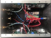
Pictures heres: ACA 1.6 - Album on Imgur First one was with everything connected up, last three after the speaker protect is disconnected.
Your multimeter should have a 'continuity' setting to measure if there is electrical continuity between to points. This usually beeps to denote continuity.
With that, you should measure that the RCAs hot plugs do not have continuity to the chassis / ground.
For the MOSFETs, you should do that between the center leg and the heatsink (I think, this probably requires some confirmation). One of the legs of Q1 should actually have continuity to ground, but only that one leg. There's for sure a more scientific approach... I'll let that one to the more advanced users, I'm sure a newbie troubleshooter.
Your multimeter should have a 'continuity' setting to measure if there is electrical continuity between to points. This usually beeps to denote continuity.
With that, you should measure that the RCAs hot plugs do not have continuity to the chassis / ground.
For the MOSFETs, you should do that between the center leg and the heatsink (I think, this probably requires some confirmation). One of the legs of Q1 should actually have continuity to ground, but only that one leg. There's for sure a more scientific approach... I'll let that one to the more advanced users, I'm sure a newbie troubleshooter.
I can confirm there is no continuity between signal hot and the chassis or gnd.
The Q1 MOSFETs are as you suggest, there is only continuity between one leg and the heatsink/chassis, and it's not the centre leg. There is no continuity between the chassis and any legs for Q2.
Thanks again Rafa
Ok,
TungstenAudio, How about +- 35V supply? is that totally out?
Thats what I have in the really nice Electrocompaniette AW50 chassis. Huge toroid transformer and 2 output windings one for each channel, including 2 rectifiers of 20000Mf per channel...
what do you guys think? if need be, I will get bigger heat sinks. (existing heat sinks are 18cmx8cmx5cm deep).
thanks
undefinedza
Ummm, I see what has probably happened...
Looking at the first picture, with the delay board fitted, both outputs are shorted to ground.
Remember before you installed the delay board, the blue wires went to the Red speaker socket from the + OUT pads on the ACA boards. (This is a bit confusing as the + OUT pads are actually at 0 / GND volts.)
And the Black wire went to the Black socket from the - OUT on the ACA boards. This is the actual 'output' and NOT the ground connection.
Now if you look at the delay board picture the Blue wires from the Red sockets go to the GND terminals between ROUT and LOUT. That is correct, the blue wires are at 0 or Ground volts. So now the GND terminals between RIN and LIN are now at 0 volts too.
Unfortunately you have connected the Black 'output' wires from the ACA (- OUT pads) to the GND terminals causing a short ... It should have been the red wires from the + OUT pads connected to them. A bit confusing as I said.
What next?
Do both Q1 and Q2 get hot or just one?
Look at the Troubleshooting section 56 in the build guide for typical voltage and resistance readings. Let us know what you get.
Best go from there, Alan
Attachments
Just to be clear, since the ACA is a single-ended amp, your supply rails would be +35V and 0V. (An actual +/-35V supply would be more F5 v3 Turbo territoryOk,
TungstenAudio, How about +- 35V supply? is that totally out?
Thats what I have in the really nice Electrocompaniette AW50 chassis. Huge toroid transformer and 2 output windings one for each channel, including 2 rectifiers of 20000Mf per channel...
what do you guys think? if need be, I will get bigger heat sinks. (existing heat sinks are 18cmx8cmx5cm deep).
thanks
") )
)Given a +35V supply you would need to take the precaution of limiting the voltage to the Q4, the input JFet. At that voltage it is time to look at Mark Johnson's scheme for using a 10V Zener diode above the Drain of Q4. Since the Source of the JFet will be about 3.5V above ground, you would be back in the safe operating region for the 2SK170.
@petrnyc
Now that you are thinking about voltage and heatsinks, it’s also time to think about the current needed to drive your speakers. The quiescent current in the class A output stage will need to be greater than this.
The stock ACA runs at about 1.45 to 1.5 Amps. I run mine at 1.6 Amps. Figuring out your current requirement will also help determine how big your heatsinks need to be.
it is hard not to make the Camp amp not work....
Tony,
That's a double negative, but I think we know you mean, ''it is hard not to make the Camp amp work...''.
I guess the majority of builders do have a fully working ACA first time by following 6L6's excellent Build Guide.
But considering this is often the first kit for many builders, there have to be some failures... (Mostly poor soldering / part in wrong places etc.)
Out of interest, does someone, Jason or Jim know how many kits have been sent out? It might give a clue as to the success rate?

undefinedza
Ummm, I see what has probably happened...
Looking at the first picture, with the delay board fitted, both outputs are shorted to ground.
Remember before you installed the delay board, the blue wires went to the Red speaker socket from the + OUT pads on the ACA boards. (This is a bit confusing as the + OUT pads are actually at 0 / GND volts.)
And the Black wire went to the Black socket from the - OUT on the ACA boards. This is the actual 'output' and NOT the ground connection.
Now if you look at the delay board picture the Blue wires from the Red sockets go to the GND terminals between ROUT and LOUT. That is correct, the blue wires are at 0 or Ground volts. So now the GND terminals between RIN and LIN are now at 0 volts too.
Unfortunately you have connected the Black 'output' wires from the ACA (- OUT pads) to the GND terminals causing a short ... It should have been the red wires from the + OUT pads connected to them. A bit confusing as I said.
What next?
Do both Q1 and Q2 get hot or just one?
Look at the Troubleshooting section 56 in the build guide for typical voltage and resistance readings. Let us know what you get.
Best go from there, Alan
Yes! This was it. Thank you.
I did the impedance measurements in section 56 and found that things were more or less correct. Then switched the outputs around as you suggested, and bam, it's singing again.
Very impressed that it survived that!
Now rebiasing to 12V before closing it up
Thank you very much Alan4411 and RafaPolit for the help.
I think he meant its not hard not to make the Camp amp not work
At the risk of being perceived as flogging a dead horse, I think it should be: "It is hard to make the Amp Camp Amp not work."
And I agree with that statement. Even after designing my own PCB's in KiCad (with minimal electronics knowledge) and also not having access to Mouser or DigiKey components, mine worked first time. But then, it is quite a simple circuit. What could go wrong? ...apart from bad soldering.
- Home
- Amplifiers
- Pass Labs
- Amp Camp Amp - ACA