The 0.563 is the important one. That seems to show that the current regulator transistor is biased correctly but you need to follow this through because you mention that the heatsink was cold.
Look at the circuit... you should measure a voltage of approximately 0.9 volts between Q2 source and Q1 drain. This is the voltage across the four big resistors. Now if that is present then the heatsink should be getting hot because that implies significant current is flowing in the resistors.
The voltage across R15 is derived from that 0.9 volts.
Voltage between Q2 source and Q1 drain is 0.863 v
I don’t think I did a good job of explaining what is going on
The amp is now heating up and has been since for all of the measurements I have done ( see files from above )
The only time it did not operate properly was when the left/white channel shut down when I hooked up a preamp and 6 ohm speakers
It ran for about a minute or two and then the left/white channel shut down
I then shut everything off and unplugged the preamp and speakers
I turned it back on an hour later —- still no left/white channel
The next day while still not hooked up to preamp or speakers the left/white channel started to work again
I have not hooked it back up under a load since then — but it appears to be ok?
Not sure I trust this amp at this point
I appears to be intermittent issues
Thank you KW
It does all sound like some intermittent connection somewhere.
As a pretty good generalisation, if the 12v midpoint is OK and the heatsink is warm/hot (the 0.863v you mention above is directly related to the current flow... and that value is fine) then all the DC conditions are correct and any lack of audio could be an issue with either input or output wiring,
As a pretty good generalisation, if the 12v midpoint is OK and the heatsink is warm/hot (the 0.863v you mention above is directly related to the current flow... and that value is fine) then all the DC conditions are correct and any lack of audio could be an issue with either input or output wiring,
Hi guys, new to making a DIY amp. I am interested in making a couple of these with my son. We currently have JBL 3800 speakers, with a listed sensitivity of 92db and measured usually around the 90-91db range. Do you think this will be sufficient to power these speakers? When answering this question, are there other important variables needed to be considered? My listening volumes are usually moderate or low. Thanks for any help!
I would call 92db 1watt/1m pretty high tbh and so I wouldn't foresee any issues at all tbh. Most listening happens at only around a volt or two of drive,
Have a read at this and give it a try if you want to know how much 'power' you need:
https://www.diyaudio.com/community/...h-voltage-power-do-your-speakers-need.204857/
An ACA in normal stereo mode will put out around 7 volts rms
Have a read at this and give it a try if you want to know how much 'power' you need:
https://www.diyaudio.com/community/...h-voltage-power-do-your-speakers-need.204857/
An ACA in normal stereo mode will put out around 7 volts rms
Thanks, this is great, I think we should be fine at usual listening levels.I would call 92db 1watt/1m pretty high tbh and so I wouldn't foresee any issues at all tbh. Most listening happens at only around a volt or two of drive,
Have a read at this and give it a try if you want to know how much 'power' you need:
https://www.diyaudio.com/community/...h-voltage-power-do-your-speakers-need.204857/
An ACA in normal stereo mode will put out around 7 volts rms
Question about using one of the Meanwell LRS switching power supplies inside an amp camp.
With the PSU inside the amp, should the AC mains go directly into the LRS, then the V+ DC current to the switch and split off to both amp boards?
Or should the AC Live signal go to the switch for turn on before the Meanwell LRS?
Thanks! I bought the LRS 24V 4.5A version because of its size so hoping this one works.
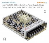
Are you thinking about one of these in the chassis? Would it cause noise! Mean Well LRS-100-24 Switching Power Supply, Single Output, 24V, 4.5A, 108W, 5.08" L x 3.82" W x 1.18" H https://a.co/d/0CdQ4LBQuestion about using one of the Meanwell LRS switching power supplies inside an amp camp.
With the PSU inside the amp, should the AC mains go directly into the LRS, then the V+ DC current to the switch and split off to both amp boards?
Or should the AC Live signal go to the switch for turn on before the Meanwell LRS?
Thanks! I bought the LRS 24V 4.5A version because of its size so hoping this one works.
PictureAre you thinking about one of these in the chassis? Would it cause noise! Mean Well LRS-100-24 Switching Power Supply, Single Output, 24V, 4.5A, 108W, 5.08" L x 3.82" W x 1.18" H https://a.co/d/0CdQ4LB
Attachments

Yes I’d put a switch in the live AC wire in with a fuse to the Mean Well unit.Yes. That exact one. I know it’s .5 amps less than the meanwell PSU. My question was where in the chain the power switch go.
Between the AC and the meanwell?
Or after the meanwell before the amp boards?
And it is so inexpensive!Yes I’d put a switch in the live AC wire in with a fuse to the Mean Well unit.
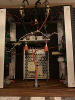
Agreed! I just installed it with a switch before the PSU and a switch between the PSU and amp boards. Works great. I didn’t think about a fuse and will need to add later.
It hummed quiety on my work bench but is silent in my office. Probably the light above my bench.
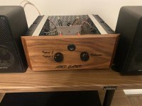
Just setting it up now for a quick listen on some test speakers.
It hummed quiety on my work bench but is silent in my office. Probably the light above my bench.
Just setting it up now for a quick listen on some test speakers.
Attachments
Here's a question:
When Nelson Pass recommends a Mean Well SMPS for the ACA, why is it my (our?) natural inclination to want build a linear CLCLC supply?
And the follow up, why CLC when even Pass Labs brazzilion dollar amps use CRC (I think)?
And choke input need not apply?
When Nelson Pass recommends a Mean Well SMPS for the ACA, why is it my (our?) natural inclination to want build a linear CLCLC supply?
And the follow up, why CLC when even Pass Labs brazzilion dollar amps use CRC (I think)?
And choke input need not apply?
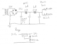
So I'm thinking a PS as attached. Each regulated supply will feed a board at 24v 1A.
The Hammond 155B's are rated at 2A, so right at the limit. And they have 0.3 resistance.
I have a handful of 317T's lying around and these are rated at 1.5A's so that is why I have the last cap feeding two regulators.
I've not been successful using spice. And not sure about the results of a pi filter (much less CLCLC). I'm used to milliamps for tube power supplies and big chokes - my reference being Morgan Jones' books.
Anyone want to throw some darts at this?
Thanks,
Dan
Attachments
Looking at the engineering datasheet from the LM317 manufacturer:
And you might want increase the inaccuracy figure by another 2% because the external resistors, 200 ohms and 5460 ohms, are probably 1% tolerance parts each.
I suggest getting rid of the inductors and/or using four individual low-Vfwd diodes instead of a monolithic bridge rectifier. The Field Effect Rectifier Diodes from ST Microelectronics look super wonderful. 20 amps, 100 volts, Mouser P/N 511-FERD20H100STS
- Load regulation accuracy is 1.5% of Vout thus 0.015 * 24 = 0.36V
- Minimum in to out voltage is 3.0V
And you might want increase the inaccuracy figure by another 2% because the external resistors, 200 ohms and 5460 ohms, are probably 1% tolerance parts each.
I suggest getting rid of the inductors and/or using four individual low-Vfwd diodes instead of a monolithic bridge rectifier. The Field Effect Rectifier Diodes from ST Microelectronics look super wonderful. 20 amps, 100 volts, Mouser P/N 511-FERD20H100STS
- Home
- Amplifiers
- Pass Labs
- Amp Camp Amp - ACA