Yes, no point faking IRFP240.
It is definitely widely available, cheap and reliable but not the best fet for the job.
IMHO IRFP150 is a much better choice. Also a few other fets, as other members
have found out.
Check:
ACA amp with premium parts
In a nutshell higher transconductance fets perform better as Q1.
I think IRFP044 would be the best, sadly no longer available.
Also looks like that this PCB (the one with the diode) is a good candidate for high PSU voltage ACA, with a few other mods.
hello all a little help would be very appreciated
just build v1.8
the amp will play for about 45 seconds, then power itself down for about 2 seconds, then back up.
Does it regardless if music going thru it or not.
When it powers up/down, it makes a sound like my speakers are farting.
thanks!
Assuming the PSU is OK-
Try just one board at a time, disconnect the wire connected to V+ on the board.
If one side works and the other does not, fault find the faulty side.
Yes, no point faking IRFP240.
It is definitely widely available, cheap and reliable but not the best fet for the job.
IMHO IRFP150 is a much better choice. Also a few other fets, as other members
have found out.
Check:
ACA amp with premium parts
In a nutshell higher transconductance fets perform better as Q1.
I think IRFP044 would be the best, sadly no longer available.
Also looks like that this PCB (the one with the diode) is a good candidate for high PSU voltage ACA, with a few other mods.
hi Stanislav
yes the premium parts thread is very interesting, i read it partly.
why is this clone pcb good for high Voltage psu?
which mode would you do at this Zerozone pcb?
preamp...?
sorry
i do not want to blame Pass pre amps..
but anybody tried something like this cheap preamp amp pcb?
DC 12V 24V Preamplifier NE5532 Audio Decoder Voice Player Module Audio Signal Amplifier Dual Channel 4 Gain|Instrument Parts & Accessories| - AliExpress
sorry
i do not want to blame Pass pre amps..
but anybody tried something like this cheap preamp amp pcb?
DC 12V 24V Preamplifier NE5532 Audio Decoder Voice Player Module Audio Signal Amplifier Dual Channel 4 Gain|Instrument Parts & Accessories| - AliExpress
Sometimes it's fun to have a couple of controls on your power amp. Probably a DPDT switch on the front panel could switch the phase of the input signal for both channels. That would allow you to choose which phase sounds best for a particular recording. I'm not sure I'd hear the difference, but it would be interesting to find out.
This amp is labeled as a Pass design, thus we document the construction of the amp as he designed it, which is why the phase is inverted.
This amp is labeled as a Pass design, thus we document the construction of the amp as he designed it, which is why the phase is inverted.
.... there is no standard for phase on the software we listen to, the artifical swapping of the speaker terminals is only a cosmetic bandaid as one still has to figure out the absolute phase of the recording (if it is consistent, your system and ears ar eup to detecting it).
hi Stanislav
why is this clone pcb good for high Voltage psu?
which mode would you do at this Zerozone pcb?
Hi Chris,
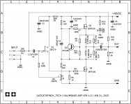
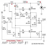
Below are the schematic diagrams of Tony Tecson's Big ACA and ZenMod's unnecessary Turbo ACA.
Instead of the diode on your PCB they have a resistor in series with the drain of Q4 so the drain voltage is reduced to a more comfortable level. To do that on the regular PCB one has to cut a trace and many people are hesitant to do such thing.
Also don't forget to add that capacitor at the node, I think it's missing on your PCB.
There are also one or two more resistors that need to be added / changed.
All in all an easy modification but it should be a subject of a different thread so not to confuse the builders of the regular ACA.
I don't use the Zerozone pcb, but all the modes applicable to the regular ACA should be possible with this one as well. Just wire it according to the build guide.
Amp Camp Amp V1.8 Change Information - diyAudio Guides
I'm sure someone more experienced with the wiring options will chime in.
Attachments
...preamp
i found something which fit to all my Class D amps BAL/SE -SE/BAL and to boost with 6db my ACA if i use about 10-12dB gain.")
BTSB Buffer SE/Bal to SE/Bal Buffer | Etsy
XRKaudio ACP+....can i set here the gain?
ACP Preamp PCB | Etsy
chris
i found something which fit to all my Class D amps BAL/SE -SE/BAL and to boost with 6db my ACA if i use about 10-12dB gain.
BTSB Buffer SE/Bal to SE/Bal Buffer | Etsy
XRKaudio ACP+....can i set here the gain?
ACP Preamp PCB | Etsy
chris
Hi triode
Yes i did some failures about the components at the beginning..remember 1k instead of 10k...wrong sorted
at this clone pcb i measured the components but i have to try with "real" components. actually my time is hardly reduced now for audio.
pleas do not use the diode at the place of FR207. its in the Drain of the N-JFET and its useless in my opinion. the sound is then super smooth and wooly
I only use the N-JET, MOSFET IRFP240 and some resistors from this seller.
R9 for example is not 1k...1k5 i my case maybe better because of the lower current by the K30A N JFET. i need more time to recheck everything and setup the DC bias about 1/2 the supply ! sound is still very nice...
As a read nearly 470 pages of this thread i found a comment by ZEN mod that nobody fake the IRFP240 MOSEFET...and i belive he is right...there is no need. its a cheap and robust component.
chris
YES : " lower current by the K30A N JFET." That is it. There is so little current, with the source resistor the voltage buildup is not right. Not it is a very complex scheme (looks so simple . . .) because of the feedback that sort of gives a bootleg to the input.
I tried 2SL30AGR too. But I now have good 2SK170's. Any with a higher IDSS like 6,5-10 will do I think. The effect is immediate.
Hi
Stanislav wrote:
Instead of the diode on your PCB they have a resistor in series with the drain of Q4 so the drain voltage is reduced to a more comfortable level. To do that on the regular PCB one has to cut a trace and many people are hesitant to do such thing.
sorry to be nooby...
Is that because of the pinch off mode of the N-JFET area?importatn at 48-v supply also at 24V volts?
ACA(s) to drive HiVi 3.1a?
Howdy!
I run a pair of HiVi 3.1as (with perfectionist crossover mod) in nearfield. I'm considering building an ACA or two to drive them. I believe that they are still around the stock 87db sensitivity with the mod. SPL calculation seems to say I could get up to 95db at my listening position, which seems way more than sufficient.
It would be great to just run one, for desk space and budget, but I've seen it suggested that monoblocking is the way to go with these. I don't know if you get a discount for ordering more than one at the same time, so I could always start with one and build a second if I'm not happy I guess.
Does anybody here have experience with this specific setup, or similar setups? Also interested in people's thoughts about running the ACA stereo vs two monoblocks. Thanks!
hi
why is that small cap 10µF or in premium part 100µ so important?
That cap together with the resistor (2.2k or 6.8k or whatever you need it to be) forms a LP filter that filters noise for the buffer stage (Q4)
The resistor also eats some voltage at the drain of Q4 and keeps its power dissipation down and the voltage through it at some manageable level.
Maybe ask Tony why he chose those values, re. trimmer and feedback.
...HiVi 3.1… I'm considering building an ACA or two to drive them. I believe that they are still around the stock 87db sensitivity with the mod. SPL calculation seems to say I could get up to 95db at my listening position, which seems way more than sufficient.
An externally hosted image should be here but it was not working when we last tested it.
[do note the vertival scale is logarithmic whicjh makes it worse than it looks]
Do keep in mind that the speaker’s impedance will impress part of itself on the FR if the Rout is highish.
A pair of bridged ACA have Rout high enuff for it to possibly be an issue.
Less of an issue with just one (or in parallel).
dave
hi tony
thank you for your comments.
maybe you miss some posts before.
i did the DC bias setting to get an symmetrical wave = DC Setting 9,1V..... but the Q2 get therefore 15V to waste and Q2 gets 90°C
chris
life is full of compromises, you do not get something for nothing....so what is your priority? a 1/2 b+ setting or the symmetrical setting? your choice, i can not make that for you.....you decide...
this is an unsymmetrical circuit, a single ended mosfet common source loaded by an active load, a CCS....
if you want symmetry at 1/2 b+, then perhaps making the CCS a p type mosfet like the IRFP9240 may get you there....but no guarantees.....i suggest you go back and read up on Nelson Pass so you get insights as to design philosophy....
Last edited:
try to get more insights from this talk....Nelson Pass and his $327 DIY Class A amp - YouTube
Thank you Tony
As Mooly cleared this un symmetrical behavior is normally...maybe not so hard like i have....at the beginning of my journey
perhaps, what you may want to do is to match the mosfets for equal transconductance and Vgs...you will need a lot of samples though....https://www.firstwatt.com/pdf/art_matching.pdf
Last edited:
- Home
- Amplifiers
- Pass Labs
- Amp Camp Amp - ACA