@6L6
A question of two builds.
In your accounts of building Pearl 1 and Pearl 2 I noted that you used "pretty" red PRP resistors for "1" that sounded pretty good and what look like Vishay Dales for "2".
And to my eyes the PRP were 1/2 watt and the Dales, 1/4 watt. Right?
I was wondering if you could share a comparison of the two?
Perversely, I'm considering using Takman REY's to populate my Pearl 1 boards (mine are old enough not to have the grounding note on the silkscreen but the illustration in the manual had it) because they're available at Parts Connexion down the road and wondering if the 1/2 watts are worth the extra expense (lower noise)?
Thank you for taking the time to help me out with this!
So the solution is to simply increase R12 to 990 ohms?
Well, try it! I think it may have been a typo when the PASSDIY article was published, or perhaps it may have been one of those purposeful errors which make you think a bit harder.
When you determine the values for T4, then you have to go back and calculate the component values for T3 and T5. Only R12 needs adjustment.
I've been reminded that one of the most important things you can do is match the RIAA network components per channel and damn the torpedoes; Me, I appreciate the "loudness" switch on my 1970's era receivers.
mhenschel -
Comparing the two resistors;
The absolutely most important thing was that both of the series (in the two different builds) were of the proper value and in stuffed the proper positions.
To my memory both were the 1/4W version, though to be completely accurate the Dale are listed as a 1/8W or 1/10W on the datasheet because the "RN" series are MilSpec and the spec requires a 100% derating, so to meet that they take a 1/4W body and print 1/8W on the datsheet. This is consistent when comparing the Dale CMF to the Dale RN - the RN are all one body size bigger than the CMF.
The Dale RN have lead-bearing tinning on the leads because the MilSpec understands that the only way to get a genuinely stable solder joint is to use leaded solder, and the leads are non-magnetic. The PRP are RoHS.
Both the PRP and the Dale have the value printed on the sides in numerals instead of a colored band system, and this is absolutely paramount in making them DIY friendly. The Dale use a "3-digit + Multiplier" scheme for most values, I.E., "1000" would be 100ohms, (not 1K) because the value is 100+zero zeroes, =100. A 1K resistor would be marked "1001", or 100+1 zero. 10K is "1002", 100K is "1003" ...
The PRP are a little more clear, a 1K would be marked "1K" 33.2ohm marked "33R2" 475K would be "475K", so there's less ambiguity.
The Dale are pale brown with black printing and extremely easy to read. The PRP are shiny red with somewhat translucent white printing and look fantastic, particularly on a blue PCB .
As for quality, they are both the best of the best. Unquestionably. Both are available in 0.1% tolerance with 25ppm tempco. (And the guy who wants that kind of accuracy also adjusts his bow tie with a laser level... )
)
One thing with mentioning, the Dale are fantastically expensive in the real world. In quantity through distribution they are getting to be 15-20x the price of a slightly more pedestrian resistor (Yeago, Xicon, both of which I use and recommend with no hesitation) with the same paper specs. They are also getting harder and harder to find on the shelves. The PRP are boutique resistors and priced as such when you have to get them through audio channels. In real quantity (I.E., 1000+ per value) they are actually quite reasonable.
Comparing the two resistors;
The absolutely most important thing was that both of the series (in the two different builds) were of the proper value and in stuffed the proper positions.
To my memory both were the 1/4W version, though to be completely accurate the Dale are listed as a 1/8W or 1/10W on the datasheet because the "RN" series are MilSpec and the spec requires a 100% derating, so to meet that they take a 1/4W body and print 1/8W on the datsheet. This is consistent when comparing the Dale CMF to the Dale RN - the RN are all one body size bigger than the CMF.
The Dale RN have lead-bearing tinning on the leads because the MilSpec understands that the only way to get a genuinely stable solder joint is to use leaded solder, and the leads are non-magnetic. The PRP are RoHS.
Both the PRP and the Dale have the value printed on the sides in numerals instead of a colored band system, and this is absolutely paramount in making them DIY friendly. The Dale use a "3-digit + Multiplier" scheme for most values, I.E., "1000" would be 100ohms, (not 1K) because the value is 100+zero zeroes, =100. A 1K resistor would be marked "1001", or 100+1 zero. 10K is "1002", 100K is "1003" ...
The PRP are a little more clear, a 1K would be marked "1K" 33.2ohm marked "33R2" 475K would be "475K", so there's less ambiguity.
The Dale are pale brown with black printing and extremely easy to read. The PRP are shiny red with somewhat translucent white printing and look fantastic, particularly on a blue PCB .
As for quality, they are both the best of the best. Unquestionably. Both are available in 0.1% tolerance with 25ppm tempco. (And the guy who wants that kind of accuracy also adjusts his bow tie with a laser level...
)One thing with mentioning, the Dale are fantastically expensive in the real world. In quantity through distribution they are getting to be 15-20x the price of a slightly more pedestrian resistor (Yeago, Xicon, both of which I use and recommend with no hesitation) with the same paper specs. They are also getting harder and harder to find on the shelves. The PRP are boutique resistors and priced as such when you have to get them through audio channels. In real quantity (I.E., 1000+ per value) they are actually quite reasonable.
Last edited:
Well, I take it as a basic tenet that one ought to put the correct value component where it is supposed to be in the circuit to have it work properly. Otherwise what do you have? Chaos!
When I was building stuff initially -- back in the 80's mostly -- I had access to resistors that were banded (Philips) and printed (Corning RNs). For my purposes they were equally easy to read and identify correctly. I measured many of them and never found an incorrect identification of either style. Maybe that's changed since then? But errors can be made in either case just as easily.
I have to say that the printing on the RN55s sure was tiny!
Since you avoided my question about wattage I'm guessing that there's no reason to choose an RN60 -size -- which is what your PRPs looked like (like my Cornings) -- over an RN55.
Any experience with the Takmans?
By the way, where do the Vishay "naked" bulk metal foils fit into the hierarchy?
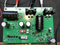
6L6 has been helping me with my boards but I thought I’d post my issue so others could chip in and maybe learn as well. I’ve completed both PCBs and get identical — and wrong — measurements. Here’s the situation.
I’m using the Chipamp PS to get 31.7V. When connected to the boards, the LED does not light and I get these measurements: At the P1 adjustment pad, I get -7.3V which does not change when turning P1’s adjustment screen. At R4, I get +2.3V instead of +24V, and at R33 I get -7.4V instead of -24V.
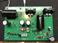
6L6 diagnosed a zapped ZVP3310 when I tested the first board, but also noted the dark LED was another issue. I replaced the 3310 and got the same measurements. I then completed the second board, being super careful with the 3310 (wrist strap, silicone rubber mat, spreading the leads only with a plastic tool) and again get the same measurements. Photos of both boards posted.
Before stuffing I checked all component values, except the transistors because I wasn’t sure how to test them anyway and was afraid of damaging them in the process.
So there we are. All input welcome, and thanks.
I’m using the Chipamp PS to get 31.7V. When connected to the boards, the LED does not light and I get these measurements: At the P1 adjustment pad, I get -7.3V which does not change when turning P1’s adjustment screen. At R4, I get +2.3V instead of +24V, and at R33 I get -7.4V instead of -24V.
6L6 diagnosed a zapped ZVP3310 when I tested the first board, but also noted the dark LED was another issue. I replaced the 3310 and got the same measurements. I then completed the second board, being super careful with the 3310 (wrist strap, silicone rubber mat, spreading the leads only with a plastic tool) and again get the same measurements. Photos of both boards posted.
Before stuffing I checked all component values, except the transistors because I wasn’t sure how to test them anyway and was afraid of damaging them in the process.
So there we are. All input welcome, and thanks.
Attachments
Last edited:
6L6 has been helping me with my boards but I thought I’d post my issue so others could chip in and maybe learn as well. I’ve completed both PCBs and get identical — and wrong — measurements. Here’s the situation.
I’m using the Chipamp PS to get 31.7V. When connected to the boards, the LED does not light and I get these measurements: At the P1 adjustment pad, I get -7.3V which does not change when turning P1’s adjustment screen. At R4, I get +2.3V instead of +24V, and at R33 I get -7.4V instead of -24V.
6L6 diagnosed a zapped ZVP3310 when I tested the first board, but also noted the dark LED was another issue. I replaced the 3310 and got the same measurements. I then completed the second board, being super careful with the 3310 (wrist strap, silicone rubber mat, spreading the leads only with a plastic tool) and again get the same measurements. Photos of both boards posted.
Before stuffing I checked all component values, except the transistors because I wasn’t sure how to test them anyway and was afraid of damaging them in the process.
So there we are. All input welcome, and thanks.
Your voltage regulators are not putting out the correct voltage so nothing downstream is going to be right - you need to fix that. Confirm + and - voltages from the power supply are correct and confirm correct orientation and correct parts for the regulators.
I can’t believe I did that. Swapped 7924 and 7824, both boards. But I have spares! Many thanks.

It’s not my fault! The 7824 and 7924 are in the wrong bags from Mouser!! OK, so I should have checked. Still, I’ll not take that for granted again. Unsoldering these things is painfully slow.
Stuff happens. A great desoldering tip I got from here is to ADD solder if you're having trouble. Add a ton of solder, then heat till it starts to bubble, then hit it with the sucker. I use a spring-loaded one.
Unsoldering these things is painfully slow.
Having recently desoldered transistors from a Pearl, I sympathize. I could not get a solder sucker in close enough to the tiny leads to get it to work and even solder wick was mostly useless. I clipped the old components leads so that I could pull them out one at a time, then used the leads on a few sacrifice resistors to poke out the clipped bits. After several rounds of heating and inserting the sacrificial resistor leads, wiping them with the iron and solder wick, then flossing the lead in and out of the hole, I was able to remove enough of the old solder to restore a hole. It was tedious, but by heating only the leads instead of the pad, I managed to avoid lifting any pads.
Stuff happens. A great desoldering tip I got from here is to ADD solder if you're having trouble. Add a ton of solder, then heat till it starts to bubble, then hit it with the sucker. I use a spring-loaded one.
No, no, no...get yourself a rosin pen from MGChemicals. You can easily find them in the DIY section of MicroCenter stores here in the States.
Overheating boards, even FR4 gets ya into trouble.
Hello,
I finished my Pearl 2 about a week or so ago. I ended up using an extra Yarra preamp power supply I had built a while back. The Pearl 2 sounds very good and is very quiet. The Yarra is a capacitance multiplier power supply, and because it is not regulated I built the Pearl 2 boards with their RC filter and regulators in place. Not knowing anything about power supplies, should I be aware of any possible negative interaction between the cap mx power supply and the Pearl RC filters?
Thanks!
Hi Everyone,
Thank you for the wonderful resource that is this thread! Some beautiful and ingenious examples in the many pages here. I'm Getting back into DIY after about 10 years, i've been reading, making notes, and ordering all the supplies for my (quarantine inspired) Pearl 2 build. I'll post some photos of my workspace, as well as build progress and questions as i go along.
Excited to be getting back into it, and can't wait to hear what the Pearl sounds like. planning to build it with the stock values and then tailor from there (thanks Jackinnnj for the alternative RIAA modelling you've presented). Using the (way oversized) universal PSU from the store, it's a lovely looking board and i didnt want to bother with perfboard for this one.
Cheers!
Ah, all is well. Out with the bassackwards regulators and in with the correct ones. Lights on, correct voltages. One PCB drifts between +-75mv and was easy to trim at P1, but the other drifts more And is more sensitive to adjustments. I’m letting it just run a while after getting the swings down to about +-200mv to see if it settles down.
Ah, all is well. Out with the bassackwards regulators and in with the correct ones. Lights on, correct voltages. One PCB drifts between +-75mv and was easy to trim at P1, but the other drifts more And is more sensitive to adjustments. I’m letting it just run a while after getting the swings down to about +-200mv to see if it settles down.
I just built mine (without reading this thread first), and had similar swings and not such great sound, so I started reading the thread. I realized that I shouldn't have included C7, took it out, and the offset swings settled way down and the sound was much better.
I went back to my boards one last time. But before measuring offset, I looked at every solder joint under my magnifier light and reflowed any that looked at all iffy. If I didn’t see a nice solder bump on the top side, I did it again with a freshly tinned iron. And what do you know? Both boards are now +-1.5 mV and move slowly in that range.
I thought back to the Steve Guttenburg Audiophiliac interview with Wayne Colburn and Nelson Pass. They’ve worked together 30+ years, Wayne on small signal kit and Nelson on power amps. Makes me think The Wizard’s Assistant knows how to design and we just have to be up to the task of a clean build. Then try some variation.
I can’t believe those guys make these toys available to us. Cheers.
Can’t wait to hear it.
I went back to my boards one last time. But before measuring offset, I looked at every solder joint under my magnifier light and reflowed any that looked at all iffy. If I didn’t see a nice solder bump on the top side, I did it again with a freshly tinned iron. And what do you know? Both boards are now +-1.5 mV and move slowly in that range.
Glad you got it sorted! Makes me want to check my work as i go!
Pass DIY Addict
Joined 2000
Paid Member
Premium Blue Desoldering Pump Solder Sucker from ubld.it Electronics on Tindie
You want this huge one, it moves a lot of air.
Also, people new to desoldering don't realize that you need to keep the iron on the joint at the same time as the sucker. If you remove the iron before placing the sucker the solder will freeze. The tips are made from Teflon for a reason...
You want this huge one, it moves a lot of air.
Also, people new to desoldering don't realize that you need to keep the iron on the joint at the same time as the sucker. If you remove the iron before placing the sucker the solder will freeze. The tips are made from Teflon for a reason...
- Home
- Amplifiers
- Pass Labs
- Building a Pearl 2