Sure, no problem.
Note: BOM does not include C7, any R20 input loading resistors or any additional input loading capacitors. Power supply is a separate BOM that would be based on builder's preferred design.
Note: BOM does not include C7, any R20 input loading resistors or any additional input loading capacitors. Power supply is a separate BOM that would be based on builder's preferred design.
I highly recommend Wayne's ps. It's easy with a small enclosure and some hot glue to secure the caps. ...listening to Thievery Corp vinyl as I type!
I’ve finished all my wiring and let my Pearl 2 idle overnight. After bragging earlier that I had gotten my DC offset measures low and stead after completing just the boards, I now get +- 70mv on the left board and +- 20 mV on the right. Also, while I get a steady 24.0V out of the regulators, I’m down 2V across R6, instead of 1.5V. Then, I’m at 20V at R9, close to the recommended 20.2, but I fall to 7.5V (left) and 8.4v (right) at the top of R11, where I’m supposed to get 10.1V. I’m also low at the 10V point that I’m measuring as the bottom of R8, with 8.1V left and 8.9v right.
Seems pretty far off to me, but I’m not that experienced.
Seems pretty far off to me, but I’m not that experienced.
I’ve finished all my wiring and let my Pearl 2 idle overnight. After bragging earlier that I had gotten my DC offset measures low and stead after completing just the boards, I now get +- 70mv on the left board and +- 20 mV on the right. Also, while I get a steady 24.0V out of the regulators, I’m down 2V across R6, instead of 1.5V. Then, I’m at 20V at R9, close to the recommended 20.2, but I fall to 7.5V (left) and 8.4v (right) at the top of R11, where I’m supposed to get 10.1V. I’m also low at the 10V point that I’m measuring as the bottom of R8, with 8.1V left and 8.9v right.
Seems pretty far off to me, but I’m not that experienced.
Concerning the DC drift, I’d consider the mod that McQuaide mentioned in #2003. That said, I remember having that kind of drift before this mod and it not being an issue. Coupling cap at the output takes care of it.
Got 2 questions
1 24va transformer good enough?
2. What if I use a Sigma 22 supply? Anybody tried using something different than the 7924 7824?
1 24va transformer good enough?
2. What if I use a Sigma 22 supply? Anybody tried using something different than the 7924 7824?
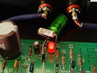
Start-up #1: right channel fuzzy. Left dead. Here’s a photo. I can hear hum at 12 o’clock on the right. The fuzzy happens at about 10 o’clock on a moderate volume. I hear nothing at all on the left. Checking input and out connections. BTW, the switch on the front panel is only connected to LED.

Last edited:
Just an experience I have.
I always quickly solder my transistor to lower temperatures and usually it doesn't go through the holes. I had instances before too high heat ior too long t makes the transistor acts funny
I always quickly solder my transistor to lower temperatures and usually it doesn't go through the holes. I had instances before too high heat ior too long t makes the transistor acts funny
Start-up #1: right channel fuzzy. Left dead. Here’s a photo. I can hear hum at 12 o’clock on the right. The fuzzy happens at about 10 o’clock on a moderate volume. I hear nothing at all on the left. Checking input and out connections. BTW, the switch on the front panel is only connected to LED.View attachment 845001
I had similar problems that disappeared when I went around and touched up all the solder pads from the top as well as the bottom, paying close attention to the ground plane connection pads.
I used a heat sink clip on all semiconductor leads between the pad and the component body to prevent damage. I also had oscillation at 4MHz on the scope until I removed C7.
Concerning the DC drift, I’d consider the mod that McQuaide mentioned in #2003. That said, I remember having that kind of drift before this mod and it not being an issue. Coupling cap at the output takes care of it.
There is a drain current/Vgs "optimum" at which the gain will remain constant with respect to temperature. This point may not be convenient for the Pearl design with the 2SK170. See Erno Borbely's article:
JFETs: The New Frontier, Part 1 | audioXpress
I haven't tested my Pearl for this effect. Will have to nab the wife's hair blower.
That's an outstanding article!
Test #2: Found a solder bridge that revived the dead left board. But its sound Is very muted. Right channel has very distorted sound -- a fuzzy static kind of layer to the music, worse on treble — and audible hum at 12 o’clock. I’m using a shielded mic cable and Neutrik 4-pin XLRs for my umbilical. My power supply is a Gainclone PS board with an Antek 22/22 50VA toroidal.
All my voltage measures are very close to recommended levels, so I’m disappointed. I gave each board a good going-over in search of bad joints.So far it’s built to the design.
One last thing. My boards and JFETs came in clear bags — not anti-static bags. Was that OK? All my other transistors From Mouser and Digikey have been in anti static bags.
Is your cable shield grounded?Test #2: Found a solder bridge that revived the dead left board. But its sound Is very muted. Right channel has very distorted sound -- a fuzzy static kind of layer to the music, worse on treble — and audible hum at 12 o’clock. I’m using a shielded mic cable and Neutrik 4-pin XLRs for my umbilical. My power supply is a Gainclone PS board with an Antek 22/22 50VA toroidal.
All my voltage measures are very close to recommended levels, so I’m disappointed. I gave each board a good going-over in search of bad joints.So far it’s built to the design.
One last thing. My boards and JFETs came in clear bags — not anti-static bags. Was that OK? All my other transistors From Mouser and Digikey have been in anti static bags.
The Unraveled umbilical Cable shield is grounded to the XLR connector ground tab on the Pearl 2 chassis only (not the PS) and then to star ground on the steel bottom. I think it shows in my photo.
I decided to approach my problems with distortion by going back to the beginning. I got stable, low mV readings at the P1 test point earlier but can’t anymore. So I’m going to achieve that first. I initially thought stability was a matter of temperature; if I left it powered up an hour or so I got good readings. That’s not true now. I get a different readingS every time I test. Often Initial readings are in the range of several hundred mV on both boards and must be lowered using P1.but they still oscillate in the +-70mV range.
I’m inclined to try the capacitor fix, but I’ve seen at least two different posts on that. One calls for a 47uF/25V cap between R14 and ground. Another calls for a 400uF/25V cap in series with R14 and then bypassed with a Silmic or similar. to quote a post here. Can anybody suggest the best approach, and include physical contact points for these components.
Let me ask this: I wanted a low profile so used a 1U Galaxy chassis. It has a 40mm internal height. I used 3/16-inch standoffs from the steel bottom cover. I’m satisfied there is no contact below the PCB or with the top cover by any Bare wire or component
I’m inclined to try the capacitor fix, but I’ve seen at least two different posts on that. One calls for a 47uF/25V cap between R14 and ground. Another calls for a 400uF/25V cap in series with R14 and then bypassed with a Silmic or similar. to quote a post here. Can anybody suggest the best approach, and include physical contact points for these components.
t
I used the first approach and it worked perfectly.
Thanks, Mark. I don’t have anything that size, just some extra 22uF/25V Silmics. But when I do get one, where do I attach the cap? Across the leads of R14? Looks on the circuit that it goes to ground. I haven’t done anything “off-label” before.
- Home
- Amplifiers
- Pass Labs
- Building a Pearl 2