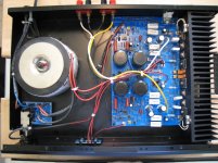
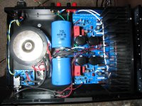
My two DIY amp projects, F5 and BA w BJT outputs have stalled for now, but look what fate (and craigslist) brought to me: a cute little Adcom GFA-5200 (an all-mosfet amp which NP designed, so that's why this post is here). I especially wanted the 5200, as it has a single output transistor per rail (whereas the 5300 has duals) and a single pcb with lots of empty space to work around. This will make a nice little summer amp to drive the top of my ESL hybrids, especially once I've completed my to-do list.
After a major vacuum, minor check-up, and revealing photo-shoot, I've punished it for over a week (making sure to test and re-test the thermal protect) playing the SL3's full-range. So far, no real guts in the bass and not so silky highs in stock form, but it shows promise.
Any chance of someone showing me a schematic?
Here's my immediate wish-to-do list:
Replace all the electrolytics
More PS caps (in the space thoughtfully reserved for them)
Thermistor to protect switch
New rectifier bridge made from 15A soft-recovery On-Semi MSR diodes and moved off-board
Re-route input leads (as they now take the scenic route close to the transformer!)
Long-term:
More heat sinking (and maybe redesign the cover to yield more space)
Bottom-mounted fan in silent housing
Transistor clamps + Kerafol insulators
More bias
Transformer-shielding and chassis-bracing steel plate
Attachments
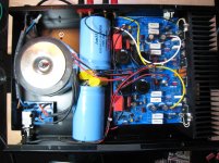
Stage One was completed about a week ago (see pic): I added two old 31mF caps to the PS, swapped all the electrolytics for a mix of Elna RFS and Panasonic FC, and squeezed in a 2u2 WIMA as input cap. Bass is noticeably tighter, but the highs are still not so smooth.
And Stage Two was completed a couple of days ago: I took the rectifier bridge off the pcb and made another bridge from 8A OnSemi MSR diodes. Also, the bias and DC offset pots were changed for Murata multi-turns. Now it sounds better in the highs, and I expect it will get even better when I add some heat sinking and raise the bias. Over the next few days I'll raise the bias a little with the stock heat sink and hear what happens....
Does anyone know the factory bias setting? It's currently set at 0.11A.
I'm considering swapping the 3W 0R1 emitter resistors for 5W Ohmite 10 Series axial wire element current sensing resistors (as they're available at DK and in my price range).
Then when Apex Jr gets in some 50V Panasonic caps I'll replace the four 6800uF in the PS and add a 0R25 in a CRC. And I have some old heat sinks to add to the stock hs and make another cover (and forgo the fan).
Attachments
I'm interested in your project. I am impressed that you squeezed those large electrolytics in that small package. I bought a beater 5200 off eBay and I am trying to get it operational. If I can get it working, I might try some of your upgrades. I don't suppose you have a schematic for this thing? I've searched in vane and found nothing other than an incomplete service manual from hifiengine. I'm forced to use the schematic for a 5300, which is similar. Good luck and I'll be following your progress.
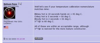
I would bias it until the sinks run 50 deg C after an hour or two. If you don't
have a thermometer, this would be the temperature that you can leave your
hand on the sink for 10 seconds.
😎
have a thermometer, this would be the temperature that you can leave your
hand on the sink for 10 seconds.
😎
Last edited:
I'm glad you're interested, jsfinusa!I'm interested in your project. I am impressed that you squeezed those large electrolytics in that small package. I bought a beater 5200 off eBay and I am trying to get it operational. If I can get it working, I might try some of your upgrades. I don't suppose you have a schematic for this thing? I've searched in vane and found nothing other than an incomplete service manual from hifiengine. I'm forced to use the schematic for a 5300, which is similar. Good luck and I'll be following your progress.
No, I have not seen a schematic for any of the Adcom mosfet amps in this series.
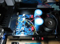
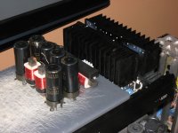
A future option is standing up the PS caps, so they will balance the look once there is more HS added (in the manner shown, but with an additional HS opposite it).
Attachments
I would bias it until the sinks run 50 deg C after an hour or two. If you don't
have a thermometer, this would be the temperature that you can leave your
hand on the sink for 10 seconds.
😎
Thank you, Nelson! I think I'm pretty adventurous (and patient!) with dialing up the bias, so I'll report back my findings. (I will probably put in some Kerafol insulators before getting too wild...)
Bias is at 0.25A (stock was 0.11A), and it sounds much better in the highs, but still not there somehow. So I'm going to R&R the 3W sand cast 0R1 emitter resistors. Would it be OK to go even lower in value here, say, 0R15//0R15 = 0R075? (That opens up options of using 2W resistors.) What is the emitter resistors' purpose?
Since this is an AB amp, I can't quite yet turn up the bias as far as NP suggests, as it gets quite hot while playing loudly. So I need to add more hs (and/or install a fan, which I am reconsidering).
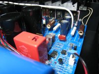
While bass control has improved with the extra 31mF caps, since I had them on-hand, I put in a couple of 68mF caps instead (as shown), so it now has six times the original PS capacitance. This further improved bass control, but I feel there's still room for improvement. And it makes me wonder why Adcom chose to use so little originally....
Since this is an AB amp, I can't quite yet turn up the bias as far as NP suggests, as it gets quite hot while playing loudly. So I need to add more hs (and/or install a fan, which I am reconsidering).
While bass control has improved with the extra 31mF caps, since I had them on-hand, I put in a couple of 68mF caps instead (as shown), so it now has six times the original PS capacitance. This further improved bass control, but I feel there's still room for improvement. And it makes me wonder why Adcom chose to use so little originally....
Attachments

Last edited:
Andersonix
I know this thread is a little old but I wanted to follow up and say I finally got my beater 5200 working. It took replacing all output devices and several small electrolytics to restore operation.
In the discussion about bias, I set mine to what is called for in the service manual: 20 mV across 0R33 (R035/R135), which is about 60mA. That is about 1/4 of where yours is set. It makes me wonder if I should set mine a little higher? My amp sounds very good and seems to work fine though it does get quite warm after 1/2 hour or so.
BTW, I used the schematic from the 5300 and it is close enough for troubleshooting the 5200. At this point, I will live with mine the way it is though I may eventually follow your lead with some of your tweaks.
Thanks for posting your mods and pics.
Well done on getting yours working, jsfinusa!
If you are referring to the Adcom service manual for the 5200, then beware: Adcom was sloppy in editing the service manual for the 5300 to create the one for the 5200, and there are errors. Note that the source resistors (R035, R036, R135, R136) in the 5200 are 0R1 (on mine at least) and not 0R33 as in the 5300. Also, while the part numbers are correct, the biasing directions (20mV across R35) are taken from the 5300 and if followed will lead to more bias than intended. The bias on my 5200 when I got it was 0.1A. In your case, jsfinusa, 20mV/0R1 is 0.2A of bias...
With the stock heat sinking, I biased my 5200 to 0.25A, and it ran warm with the cover off. Now, with more heat sinking added, I have it adjusted to 0.4A (28mV over my new 0R07 emitter resistors), and it runs warm to hot.
Since I didn't want to go back inside again, I decided to throw almost everything at my 5200: IEC connector, RCA sockets, caps, resistors, wiring, jumpers....
It now has 2x 15000uF in place of the original 2x 6800uF per rail, as well as 0R25 in a CRC (68000uF + 0R25 + 15000uF + 15000uF per rail) for over 7 times the original PS capacitance. For inrush protection, it already had a 2R5 NTC on the switch pcb, which is enough to prevent the stock fuse from blowing at turn on.
Since I didn't have the schematic, I decided to change only the emitter resistors from 0R1 to 0R07 and leave the circuit otherwise mostly unchanged (except for different type caps and resistors here and there).
Next I would like to add some inductance in a CLC for the PS and modify the cover so it fits over the new heat sinks.
With the extra heat sinking added, I have the bias set as high as I dare: 0.4A (5W of class A into 8 Ohms), but it takes over an hour to reach a stable temp and sound its best. It keeps sounding better with more and more bias, so I suppose it's time to move on to real class A amps....
Attachments
Andersonix
Thank you for your comments about the service info and biasing. My 5200 is working well, runs reasonably cool, and I really like the way is sounds. So much so that I swapped it in place of my ST70 tube amp and my whole system sounds better. I was amazed! Who would have thought a $25 broken beater amp from eBay would end up replacing my main system amp.
I did add a small PC type fan under the 5200 which forces air up through the heat sink fins. It is just glued on with some RTV and it works very well. Anyway, I am enjoying the amp and really appreciate folks like you sharing your experiences.
Best regards
jsfinusa: Indeed there is some potential bottled up inside the 5200!
If you're confident in the state of your thermal insulators (and its location is cool enough) I suggest aiming for about 0.25-0.30A of bias with the stock heat sink. And since the HS is mounted to the bottom panel for extra heat rejection, raising the amp with some taller feet (like the 1.5 inch tall ones from ApexJr that I'm using) helps air get underneath. I had left myself the option to add two small fans (stuck on with double-sided foam tape to prevent noise), but I don't think I need them for now.
Updates to my 5200: As cooler weather descended, I adjusted the bias to 0.5A (that's 8W of class A), and it improved even further (with possibly some margin for even more bias -- I will aim for 0.65A next time).
Finally, as planned, I connected a couple of 9mH (~0R6 DCR, 19AWG) inductors from ApexJr in place of the 0R25 resistors to make a CLC: Ripple on the rails went from about 4mV to about 2mV, and rails went from +/-40.6V to 39.1V. CLC (CLcc, really) is 68mF + 9mH (0.6DCR, 19AWG) + 15mF + 15mF. The improvement in the highs and low level resolution from this quiet PS was beyond my expectations. Let's just say this amp is no longer the bottleneck in the system...
But it's clear this will never be a great bass amp: Bass is slightly mushy and impact-less compared to my hot-rodded Acurus with paralleled output transistors and similar PS. But that's alright, as it was primarily intended to drive just the ESL panel in my hybrids, which it does really well -- without the 'distortion alert' lights flashing too much!
More pics to follow when a new cover is completed.
Attachments
Quarterly Update
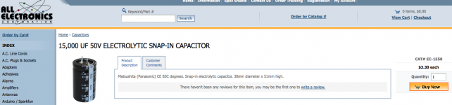
For you DIY cheapskates following along at home and working up the nerve to re-cap your own little Adcom, the perfectly fitting 15mF 50V Panasonic caps that I used for my 5200 are on sale for about $3 at AllElectronics (see attached), which is less than half the 'retail' price. If memory serves, the 535 also takes this size caps (30mm Dia, 50mm H).
I have now dialed up the bias to 0.7A (over 15W of class A into 8R), and now the HS runs hot, so hot that I can barely hold it for 10 seconds. And after about an hour it sounds glorious, despite the PS ripple going up again to ~4mV. So now I'm battling to get the ripple down again, and thinking about working in some more caps into the new cover (see attached), so that it will have a total of 128mF per rail -- 9.4 times the original! Also I want to find a tin can to put the transformer into.
Attachments
I have a 5200 which my sister is using at the moment, pristine condition and I am the only owner, since back in 97 or something. I bought it as a combo with the GFP 345.
I have since moved on to other equipment but would like some input; I am no electric DIY guy yet, but am very interested in turning up the bias and possibly add more HS. Would you recommend this and how is the bias turned up - do I need to de-solder anything or is it possible to 'adjust' it in some way?
If I could turn up the bias to get a couple of watts in class A, I might use the little amp again in either my main system or a secondary one..
Am a complete novice in doing this though so maybe it's not recommended without help from someone experienced? btw it's the 220v version as I am in the UK at the moment..
Yes, it is possible to turn up the bias without soldering anything. With stock heat sinking with the cover on in a cool place in the rack, I reckon you can go up to about 0.25A bias (which will give you 2W of class A into 8 Ohms).
I recommend you have a more experienced person helping you, as those single turn pots are very jumpy, and you could blow the output transistors. Note that the Adcom service manual for the 5200 has the bias check wrong as it's copied verbatim from the 5300 service manual. Setting the voltage at 20mV as printed will set the bias current at 0.20A (as the source resistors are 0.1 Ohm in the 5200, not 0.33 as in the 5300.)
You need a volt meter to measure voltage across one of the 0.1 Ohm source resistors. Don't do this by 'feel'!
Last edited:
hello
Prompt what electrolytes can be put in place regular power supply, without replacing the transformer?
Regards Ivan
Prompt what electrolytes can be put in place regular power supply, without replacing the transformer?
Regards Ivan
Ivan,
I replaced the 4 on-board power supply caps with Panasonic ECO-S1HP153DA from Digi-Key. They are 15,000uF 50V caps that are a perfect fit: 30mm Dia, 10mm lead pitch, and 50mm tall.
I would have gone with some caps with larger capacitance, but couldn't find any in 30mm Dia. The PS rails are about + and -42VDC, so replacement caps need to be at least that voltage rating. Hope that helps!
PS. In case it wasn't clear, I am still using the stock transformer which came with the amp.
Last edited:
Thank you for the answer.
Unfortunately in the free market in Ukrane 15,000 uF 50V 30mm diameter not have to 12000uf is 22,000 but the diameter of 35mm. Suggest that gave replacement input capacitors WIMA MKP10 2.2uf? Whether they can be removed by placing a jumper if I have a pre-amp?
Unfortunately in the free market in Ukrane 15,000 uF 50V 30mm diameter not have to 12000uf is 22,000 but the diameter of 35mm. Suggest that gave replacement input capacitors WIMA MKP10 2.2uf? Whether they can be removed by placing a jumper if I have a pre-amp?
I did not use 35mm Dia caps because it looked like they were not going to fit, especially after I squeezed in larger input DC-blocking caps. (I used 2u2 WIMA that I had on-hand. See pics in post 11)
You may choose to bypass the input caps, as long as you accept any consequences of what happens upstream to the signal! I did not want to push my luck any more than I am already...
You may choose to bypass the input caps, as long as you accept any consequences of what happens upstream to the signal! I did not want to push my luck any more than I am already...
- Home
- Amplifiers
- Pass Labs
- Summer / Consolation Amplifier: 1995 Adcom GFA-5200