Thank you! I see. Get later version of the amp, off board PSU and bias it all the way up... sounds like a plan 🙂
I designed "first copy" of the 555 and the 5800 which were then adapted
for the other models of both series, the 80's 555 series being bipolar and the
90's 5800 series being Mosfet.
Along the way, Adcom made changes of various sorts, and also changed
manufacturing, the original being Tibi and later Gallien and probably later
yet Taiwan / China. The biggest alteration was with Gallien, who apparently
simply substituted a design for the 5800 they were perhaps more familiar or
comfortable with, but which was very different.
Like Nakamichi, they did what they wanted after paying for the initial design...
I designed "first copy" of the 555 and the 5800 which were then adapted
for the other models of both series, the 80's 555 series being bipolar and the
90's 5800 series being Mosfet.
Along the way, Adcom made changes of various sorts, and also changed
manufacturing, the original being Tibi and later Gallien and probably later
yet Taiwan / China. The biggest alteration was with Gallien, who apparently
simply substituted a design for the 5800 they were perhaps more familiar or
comfortable with, but which was very different.
Like Nakamichi, they did what they wanted after paying for the initial design...
Thank you Nelson!
So then do you thin you can achieve same sound quality with just biasing less F5 (well made some other minor modifications?) amp so it transition from A to AB sooner and dissipates less heat so you need a smaller enclosure.
No. Less bias doesn't achieve the same quality as a concept. As a practical
matter, Your simpler types of amplifiers generally depend upon inherent linearity
for good performance, not having a lot of feedback to help out.
matter, Your simpler types of amplifiers generally depend upon inherent linearity
for good performance, not having a lot of feedback to help out.
Like Nakamichi, they did what they wanted after paying for the initial design...
I really wanted to say something about that but I was afraid that would come off as un-polite. I am glad you made that point. I recently worked on a Nak PA7 and saw similar after-thought mods wondering "why?" but from your comment it seems they these engineers like to use whatever black magic they can to get a different result. I only hope these mods are not a source of signal coloring.
Anyway, replaced the two MOSFETS on the channel that was on vacation and the amp is happy once again. If it had a face it would be smiling. This amp would not be at home in a situation with larger drivers or a lot of low end. The muscle and reserves are just not there. BUT it would find a very happy customer in a den or home office. For the price, on the secondary market, it represents a great value. It is easy to work on and parts are easy to source.
Also on a side note, biased at 23ma this puppy is cooking! I may put my Thanksgiving turkey on it. Surprised me for such a small amp and had me rushing back to get my meter to double and triple check those readings!
Thanks Nelson and Andersonix for the work you put forth.
Good job getting it working! I think the 5200 left the factory with about 100mA of bias. Maybe you meant 230mA?
Good job getting it working! I think the 5200 left the factory with about 100mA of bias. Maybe you meant 230mA?
I am following these docs. And I said the hell with it..throwing caution to the wind.. these MOSFETS were less than $2.00..I am going 5ma above these docs cause Nelson would have wanted it that way! Actually, from what I read Nelson likes to use these MOSFETS as space heaters 🙂
Attachments
Oops I just realized I was talking millivolts across a resistor. So I am sorry for mixing in milliamps. It is late and I have already put in 10 hours at my job!
So my voltage measurements are proportional to bias current right?
Either way at 23mv this little block of aluminum is putting out some BTU's.
I cannot do the famous 10 seconds hand measurement. Too hot. Maybe 5 seconds if I try hard.
Had me concerned for a quick minute.
So my voltage measurements are proportional to bias current right?
Either way at 23mv this little block of aluminum is putting out some BTU's.
I cannot do the famous 10 seconds hand measurement. Too hot. Maybe 5 seconds if I try hard.
Had me concerned for a quick minute.
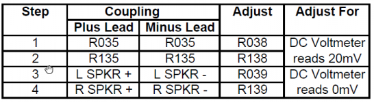
If you are referring to the Adcom service manual for the 5200, then beware: Adcom was sloppy in editing the service manual for the 5300 to create the one for the 5200, and there are errors. Note that the source resistors (R035, R036, R135, R136) in the 5200 are 0R1 (on mine at least) and not 0R33 as in the 5300. Also, while the part numbers are correct, the biasing directions (20mV across R35) are taken from the 5300 and if followed will lead to more bias than intended. The bias on my 5200 when I got it was 0.1A. In your case, jsfinusa, 20mV/0R1 is 0.2A of bias...
I'll just quote myself from post #10.
Generator labs, you have 0.023A/0.1R = 0.23A of bias, which would give you 3.7W of class A into 8 Ohms. But also you are pulling on the PS rails, and their ripple will have gone up, so much that you will not hear all your new class A glory over the extra hum.
Generator labs, you have 0.023A/0.1R = 0.23A of bias, which would give you 3.7W of class A into 8 Ohms. But also you are pulling on the PS rails, and their ripple will have gone up, so much that you will not hear all your new class A glory over the extra hum.
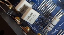
Wow, Adcom adds another layer of confusion with different board builds. These are the resistors I have:
You have done some creative things with your 5200. Probably more than I would like to do with this unit. I have the caged gorilla amps for that. I think I want to leave it Vanilla plain or maybe just replace the existing main caps with the largest that will fit there natively. Maybe visit the coupling caps in the future.
Considering that I do not have any intention of increasing the capacity of the power supply section, like you have done, where do you think I should land the mVolt reading across these resistors to keep the performance elevated but not turn it into a Barbie easy bake oven? I don't intend on using any forced cooling but I will make sure it is situated in a manner that allows good convection.
:
Attachments
Look, you're making me mix them up too! That should obviously read 0.023V/0.1R = 0.23A of bias...Generator labs, you have 0.023A/0.1R = 0.23A of bias,
I would argue that simply adding PS caps and dialing up more bias is the LEAST creative thing one can do (but also the most effective).
Everyone has to find their own comfort zone about how much heat their amp ought to give off. Or perhaps one has a target class A power number or PS rail ripple number to aim for. I don't think there's a sonic breakthrough for the 5200 until it's better than 10mV of ripple and 400mA of bias.
Everyone has to find their own comfort zone about how much heat their amp ought to give off. Or perhaps one has a target class A power number or PS rail ripple number to aim for. I don't think there's a sonic breakthrough for the 5200 until it's better than 10mV of ripple and 400mA of bias.
When I said "creative", I was referring to the various out of band mods you made such as stacking heats sinks, adding large non-PCB mounted capacitors etc. Those are not your typical mods.
If you wouldn't mind could you school me on the ripple of the PS?
Are you speaking of ripples caused by depletion of the cap bank with instantaneous demands or are you talking about leak-in ripple of mains frequency after rectification?
If you wouldn't mind could you school me on the ripple of the PS?
Are you speaking of ripples caused by depletion of the cap bank with instantaneous demands or are you talking about leak-in ripple of mains frequency after rectification?
Last edited:
One additional question:
If your 5300 has 0R33 resistors and the 5300 manual is calling for 20mV across them then the factory spec must be shooting for a bias current of .06A (0.020mV / .33 = .06A) right?
If I reverse calculate that bias into my amp with 0R1 resistors I get 6mV across the resistors. (0.1 * .06A = .006V)
Is it safe to say that if there was a correctly published service manual for the 5200 amp this would be their target? I rolled mine back to 11mV and the temp is more realistic. It is a little uncomfortable to keep your palm on the top of heat sink but at least now I can keep my hand there for a full 10 seconds.
I have a infrared temp measure device at my office. I am going to bring it home tomorrow and shoot the heat sink to see what the temp actually is.
If you wouldn't mind could you school me on the ripple of the PS?
Are you speaking of ripples caused by depletion of the cap bank with instantaneous demands or are you talking about leak-in ripple of mains frequency after rectification?
The second one, which is measured at idle: put the voltmeter on AC and measure from ground to plus rail and ground to minus rail. In stock form this ripple is about 50mVAC, and with lots more caps (and also an inductor in there for a CLC) I'm at about 6mV.
One additional question:
If your 5300 has 0R33 resistors and the 5300 manual is calling for 20mV across them then the factory spec must be shooting for a bias current of .06A (0.020mV / .33 = .06A) right?
If I reverse calculate that bias into my amp with 0R1 resistors I get 6mV across the resistors. (0.1 * .06A = .006V)
Is it safe to say that if there was a correctly published service manual for the 5200 amp this would be their target? I rolled mine back to 11mV and the temp is more realistic. It is a little uncomfortable to keep your palm on the top of heat sink but at least now I can keep my hand there for a full 10 seconds.
I have a infrared temp measure device at my office. I am going to bring it home tomorrow and shoot the heat sink to see what the temp actually is.
Yes, 0.06A per output device, so in the 5300 with 2 output transistors per rail, that's 0.12A total bias, which is about the same as the ~0.1A that I measured on both of my 5200's when I first got them.
But 0.1A of bias is just 1/3W of class A (0.12A is almost 1/2W), and I think with the amp in an open location one could run about 0.2A which would be just over 1W in class A (and then peak much higher in AB).
At some point in your hearing capabilities, the class A goodness gets swamped by the PS ripple, so that's the tug of war you've entered into here.
I forgot to post this:
When biased at 12mv I get 123 degrees F (50.5 degrees C)on the upper region of the heatsink.
I shot this measurement with an infra-red thermometer, immediately after sliding the top cover off. With the top cover off for 30 minutes the temp lowered to 113 degrees F (45 degrees C). Even with perforations in the top & bottom cover, cooling is reduced, to the order of 10 degrees F.
I believe this temp (50 C) was a target that Nelson mentioned earlier in this thread.
In my opinion, at this level, careful placement of the amp is crucial for proper convection. For me it means keeping no other component stacked on top. It is so typical to see the GFA pre-amp sitting on top of the amp in photos. I am keeping the amp on the top with an adequate gap on the bottom as well.
The sound of the amp is agreeable with me. I have pounded it pretty hard, with music and signal generator sweeps. I can easily get the yellow clipping LED's to dance but it is unrealistic to get much more out of an amp this size with the limited silicon muscles it has to push it along.
I like the way the heatsink is tied directly to the lower chassis with a number of screws however heat transfer into the floor pan is not optimal. I bet if I CNC'd a nice 10" x 10" piece of aluminum plate to form a new floor pan for the amp and tied the heat sink into that it could be more efficient. Or maybe I should just snap out of it, leave it stock and move on to more productive things 🙂
Ok so I got the amp. Later 5200 with separate psi for two channels. I am thinking now if I should just swap 4x6800uf caps for 4x22000uf, keep those on board bridges (I think the are 8A) and crank the bias up. Or... put new soft recover bridges from my FW amps off boards add 4 more caps off board to make CRC psu for each channel? Only concern is that it might be a bit too tight with that bigger board. BTW, do you actually need those 4A on the rails? 🙂
- Home
- Amplifiers
- Pass Labs
- Summer / Consolation Amplifier: 1995 Adcom GFA-5200