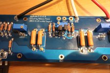
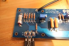
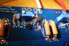
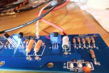
Hi still figuring out the ‘shorting problem’ in my f5build. So I replaced the MOS Fets. Isolated the rectifiers. Desoldered the output and still: when I connect my MM to the + of the output and ground there was a loud beep. Here a some pictures of my build. Sorry for the mess.
Attachments
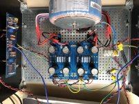
Hi still figuring out the ‘shorting problem’ in my f5build. So I replaced the MOS Fets. Isolated the rectifiers. Desoldered the output and still: when I connect my MM to the + of the output and ground there was a loud beep. Here a some pictures of my build. Sorry for the mess.
What’s the resistance in ohms between positive output and ground?
when I connect my MM to the + of the output and ground there was a loud beep.
Possibly a mounting bolt on one of the pcbs shorting a trace to the chassis.
I do see a bolt head over a trace. The solder mask can be easily cut through.
Remove the bolts and recheck.
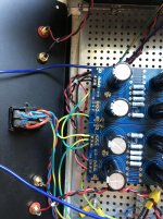
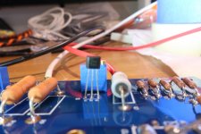
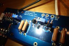
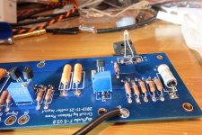
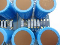
Hi. can someone please explain what is happening on the terminal block of the PSU. There are two STM CL-60 things and another blue thing in between. They're not listed on the BOM so what are they and where do I get. Also, does it matter which direction the ZTXs go, curved side yup or down? Very unclear. Thanks. I am a noob.
Hi. can someone please explain what is happening on the terminal block of the PSU. There are two STM CL-60 things and another blue thing in between. They're not listed on the BOM so what are they and where do I get. Also, does it matter which direction the ZTXs go, curved side yup or down? Very unclear. Thanks. I am a noob.
Take a look here for the orientation of the ztx transistors.
https://www.diyaudio.com/forums/the-diyaudio-store/227933-diyaudio-f5-build-guide-4.html#post5422076
Blue thingie is a line rated suppression cap, something like this:
https://www.mouser.ca/ProductDetail...3dWSqd4Tl0Lj03Gv1NDawVRIUZ0SIYpB9vZqp/C1h4g==
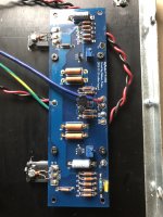
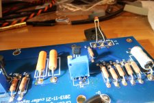
I can't figure out what I did wrong with mine. When I fire it up I'm getting 4.5v+ on one resistor and 4.5v- on the other. I shut it down instantly but I did get a bit of resistor smoke. I double checked all the part values against the schematic and the updated build guide and set the trimpots at zero.
Can anyone see what I'm missing here?
Thanks.
Can anyone see what I'm missing here?
Thanks.
Attachments
-
 IMG_1859.jpg821.7 KB · Views: 281
 -
 IMG_1860.jpg871.5 KB · Views: 269
 -
 IMG_1861.jpg881.2 KB · Views: 114
 -
 IMG_1862.jpg603.1 KB · Views: 98
 -
 IMG_1863.jpg732.6 KB · Views: 91
 -
 IMG_1864.jpg626 KB · Views: 85
 -
 IMG_1865.jpg797.5 KB · Views: 84
 -
 IMG_1866.jpg855 KB · Views: 86
 -
 IMG_1867.jpg689.5 KB · Views: 93
 -
 IMG_1869.jpg721.3 KB · Views: 101
When I fire it up I'm getting 4.5v+ on one resistor and 4.5v- on the other. and set the trimpots at zero.
Maybe the trim pots are all the way up, instead of all the way down.
Try setting them to halfway instead, but check those resistors first.
Last edited:
You used heatsink when you powered it, right?I can't figure out what I did wrong with mine. When I fire it up I'm getting 4.5v+ on one resistor and 4.5v- on the other. I shut it down instantly but I did get a bit of resistor smoke. I double checked all the part values against the schematic and the updated build guide and set the trimpots at zero.
Can anyone see what I'm missing here?
Thanks.
The trimpots are measuring 60 ohms with them in the board.
From the build guide.
''Turn all variable resistors, P1 and P2 (total of four variable resistors for a stereo
setup) fully counter-clockwise. This can be verified by measuring the resistance
between the outer leads of the variable resistors and it must read zero Ohms. This
ensures that the bias is low, if not close to zero, once we power up the amplifiers.''
clockwise did the trick with the resistance.
I flipped them over just so someday way down the road I didn't forget and turn them the wrong way.
Attachments

Hello,
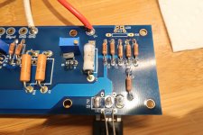
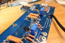
I’m slowly working away at building an F5. I got the left and right channels built, was easy thanks to the new guide (thanks 6L6). I’m working on the PSU but I want to ask before I solder a couple pieces.
The build guides photo (attached) has 10k’s installed on R9 and R10. The schematic has another value listed, the BOM specifies a range of options, and the previous poster has 22k’s in his photo. I ordered 22K OHM 3W 5% which appear to be the same as some earlier photos in this thread.
Am I OK using the 22k?
I’d like to make an educated guess to the answer based on what I think I’ve learned and perhaps you can tell me if I’m right or wrong.
..... R9 and R10 are bleeder resistors so they don’t need to be a specific value because they just change the rate of the discharge from the capacitors, so I should be fine with 22k. Is that right?
Thanks.
Attachments
")
6L6 great job on the new build guide (plus the other additions):
Firstwatt F5 amplifier v3 - diyAudio Guides
Regarding the mounting of the toroidal transformer to the front panel, shown at Step 18:
Firstwatt F5 amplifier v3 - diyAudio Guides
did you tap a threaded hole (DIY style) for that specific purpose? I wasn't aware that it's a standard feature of the Deluxe chassis front panel, e.g. the 4U interior shot:
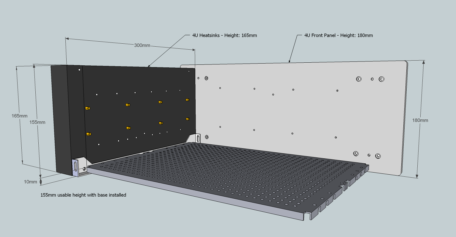
Or, did you spec it as a custom add on for the HiFi2000 crew?
Apologies if I'm commenting in the wrong place. This question could land in a couple of spots.
Firstwatt F5 amplifier v3 - diyAudio Guides
Regarding the mounting of the toroidal transformer to the front panel, shown at Step 18:
Firstwatt F5 amplifier v3 - diyAudio Guides
did you tap a threaded hole (DIY style) for that specific purpose? I wasn't aware that it's a standard feature of the Deluxe chassis front panel, e.g. the 4U interior shot:
Or, did you spec it as a custom add on for the HiFi2000 crew?
Apologies if I'm commenting in the wrong place. This question could land in a couple of spots.
- Home
- Amplifiers
- Pass Labs
- An illustrated guide to building an F5