An externally hosted image should be here but it was not working when we last tested it.
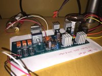
I mounted resistor under PCB - maybe its even better for "cooling"?
Ummm I cant check temperature and I suppose organoleptic checking wouldnt be enough as 40- 50C could be hot for finger
Both pair of MOSFETS get hot equally or I could get bigger heatsink for some pair? Im asking because I got bigger heatsinks but only 2 pcs")
If mounting the resistors on top they get better air circulation. All will be judged by how comfortable temperatures they develop in the end. So try as they are and see. First MOSFETS near the big electrolytics can get hotter than the next ones if the raw DC voltage goes higher than 20V across those main capacitors. Depending on how high are the transformer secondaries.
if use the sink like that ..why you use High power mosfet ,...just use small type 1-2 Amp
The MOSFETS used have a capacity for high hot-rod but they remain the same type in cooler DCB1 uses to have consistency of characteristics between all DCB1s. They can also run at about 60mA without sinking at all due to they are large (as in Zibra's original config) for simplest of construction and implementation with still very good SQ.
Friend of mine boughts these radiators at local electronic shop as I told him to buy 5W/C(?) - saw your recomendation for it in other post if I remember correct. They sell him such small ones
I found little bigger that suit first pair of MOSFETS better.
how long does it take for MOSFETS to get their biggest temperature? DCB1 running ca. 10-15 minutes and radiators on both pairs are only warm - could grab all and keep my fingers on it.
I also bougt 22R resistors so current is a little bit smaller...)
Offset is -0.5 and -2.2mV. Not superb even but I tink is ok. I removed input caps from Dynaco as there is no harm from such offset values right?
I found little bigger that suit first pair of MOSFETS better.
how long does it take for MOSFETS to get their biggest temperature? DCB1 running ca. 10-15 minutes and radiators on both pairs are only warm - could grab all and keep my fingers on it.
An externally hosted image should be here but it was not working when we last tested it.
I also bougt 22R resistors so current is a little bit smaller...
)Offset is -0.5 and -2.2mV. Not superb even but I tink is ok. I removed input caps from Dynaco as there is no harm from such offset values right?
Last edited:
how long does it take for MOSFETS to get their biggest temperature? DCB1 running ca. 10-15 minutes and radiators on both pairs are only warm - could grab all and keep my fingers on it.
I also bougt 22R resistors so current is a little bit smaller...
Offset is -0.5 and -2.2mV. Not superb even but I tink is ok. I removed input caps from Dynaco as there is no harm from such offset values right?
Since you can still grab them after say 30 minutes, no worries.
Offset can be multiplied by amp gain and change the bias a little in DC coupled precisely biased solid state amps. Even there 2.2mV isn't a real problem, mostly a matter of perfectionism. When there is an output transformer in tube power amps, no DC can pass to the speakers anyway.
Thank you Salas! Youre great and very helpful.
I connected pre now and difference is immediately shown even though my speakers XO needs some more investigation.
There is more air around vocals and sound is even more three dimensional. More dynamics and precision and highs aree more "free". Generally better sound organization and more maturity
I would say that simple tuning is a must for all owners.
So its only due to modding towards moderate hot-rod for you. Fair enough, good for symphonic and big band Latin or busy Ethnic.Not really - I removed input caps from Dynaco at renovation stage some time ago. This is effect of pure current increasing mod. Its just like after cleaning which is obvious in more demanding music where is a lot of going on

Yep, more separation less congested sound. Only some resistors left for cecking because Im curious and need to ceck all tricks by myself Know noting about volume pot influence on sound.
And nice case of course is needed
Salut Salas!
https://www.youtube.com/watch?v=0UZjZP11WDw
Know noting about volume pot influence on sound.And nice case of course is needed
Salut Salas!
https://www.youtube.com/watch?v=0UZjZP11WDw
Last edited:
So what does hot-rodding the Mez do exactly? Does it increase gain at all? I am running a DL-103R, Pearl 2, Mez and Cornwalls and on some vinyl, I could use a little more gain. Also, based on the previous pictures, I am guessing these sinks aren't sufficient for hot-rodding?
FWIW: I tried increasing the gain on the Pearl 2 and got distortion. If I place a cheap Denon 10dB SUT in front of it, the levels are about perfect, but I prefer not to use a SUT.
FWIW: I tried increasing the gain on the Pearl 2 and got distortion. If I place a cheap Denon 10dB SUT in front of it, the levels are about perfect, but I prefer not to use a SUT.
Attachments
Has not to do with the signal itself but with allowing the shunt PSUs to run better. No effect on gain either. A buffer is a unity gain circuit no matter even if golden electrons will run on its supply rails. Side effect is bit nicer DCB1 as the long term subjective testimonials insist. Those sinks in your picture maybe sufficient for 150mA. I.e. a 12R 3W single current set resistor per side.
I have a question about what is stated in this old post from AndrewT.
There it is said that output offset should be negative. The reason is to have the upper jFET not passing more than its IDSS. I would then expect having to use the lower IDSS jfet as current source so that it can set the current for the upper one to its idss which is the lowest of the two.
I've tried to study this situation with LTspice with the model I attach. I'm using there a LSK170B with idss of around 8.4 as current source and a 2sk170 with idss of around 12.4; the difference between the two is extreme but it should still capture the overall behavior.
When I run the simulation I find that both jFET run at the expected lowest idss (8.4mA) however the output offset is positive.
Am I wrong somewhere or having a positive offset is instead correct?
View attachment jFETposition.asc
With Id less than Idss, the Vgs must be negative. That's the way jFETs work.
As Vgs goes towards zero, the Id increases towards Idss.
Check your Id and Idss.
Why have you got 4 k170 models?
which ones have you used?
Have you got equivalent models for the upper and lower?
The gate current is not zero !
Check the datasheet for predicted gate current at 10Vds and cold Tj.
As Vgs goes towards zero, the Id increases towards Idss.
Check your Id and Idss.
Why have you got 4 k170 models?
which ones have you used?
Have you got equivalent models for the upper and lower?
The gate current is not zero !
Check the datasheet for predicted gate current at 10Vds and cold Tj.
Could one use the Autoformer Volume Control (AVC) from Intact Audio as a volume pot? I have problems in understanding the impedance from the FAQ.
Says they come with approximately 20 Henry inductance that dominates the reflected load. They give formula for input impedance = 2*pi*F*L. That gives 2512 Ohm for 20Hz F and 20Hy L. Your source must have no more than 250 Ohm source impedance. In case it is not enough they provide an air gap readjustment mechanical guide for more H, still 20H seems to be their recommended linearity sweet spot.
- Home
- Amplifiers
- Pass Labs
- Mezmerize DCB1 Building Thread