Marcel, what I wanted to say is that a resistor on itself causes no distortion, it is always in relation to the signal current that passes through it, and then the level of distortion depends on the driving as well as the loading impedance.
I am right there, in principle?
Jan
I am right there, in principle?
Jan
Absolutely true, but even in the worst use case, when you use the resistor as a voltage-to-current or current-to-voltage converter rather than as part of a voltage or current divider, the distortion will be much less than -67 dB because of the reasons Mark Tillotson, Vovk Z and I gave earlier.
So all in all, there are three different effects that reduce distortion below SemperFi's estimate: thermal capacity, the factors in the denominator of the distortion equations and cancellation between resistors in voltage (or current) dividers, particularly when these are made of well-matched unit resistors that all get to process the same signal level and all are mounted in a similar way.
So all in all, there are three different effects that reduce distortion below SemperFi's estimate: thermal capacity, the factors in the denominator of the distortion equations and cancellation between resistors in voltage (or current) dividers, particularly when these are made of well-matched unit resistors that all get to process the same signal level and all are mounted in a similar way.
Hello All,
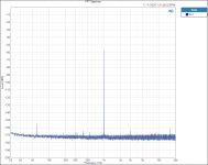
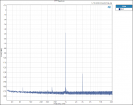
I went to Mouser.com and purchased a few PTF65 1K Ohm 0.1% 10PPM TCR resistors to do a little testing. See the attached test plots. I used the test Wheatstone-Bridge similar to the bridge used by Ed Simon.
Once you could see the harmonic peak at 3KhZ peak above the FFT noise floor it shot up quickly with increasing applied voltage. Sometimes there was a hint of a 2KhZ harmonic. Power or heat input goes up with the square of the voltage.
Note, long FFT lengths and a large number of averages reduce the apparent FFT noise floor. Also note that the levels of distortion harmonics we are talking here about are well swamped and masked by real time noise.
Thanks DT
Attachments
Hello All,
I went to Mouser.com and purchased a few PTF65 1K Ohm 0.1% 10PPM TCR resistors to do a little testing. See the attached test plots. I used the test Wheatstone-Bridge similar to the bridge used by Ed Simon.
Once you could see the harmonic peak at 3KhZ peak above the FFT noise floor it shot up quickly with increasing applied voltage. Sometimes there was a hint of a 2KhZ harmonic. Power or heat input goes up with the square of the voltage.
Note, long FFT lengths and a large number of averages reduce the apparent FFT noise floor. Also note that the levels of distortion harmonics we are talking here about are well swamped and masked by real time noise.
Thanks DT
Looks like your testsignal is almost -60dB? Is it ref 1V? So the testsignal is ca 1mV?
The TC and VC effects should only get to measurable levels MUCH bigger than that. ? Even using a CC resistor.
Could you do similar tests with large signals, and compare to 'worst type resistor' such as CC or the like?
Hello,
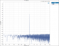
The test signal is 6.3 volts, or +16dB. That puts the 3rd Harmonic at -179dB relative to the input voltage.
Using 0.1% resistors allows for a deep null across the bridge.
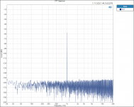
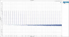
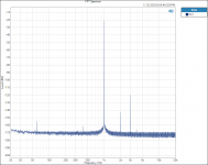
See the attached plot with 20.0V +26dB input.
Note this is sort of proof of concept or not. There are 10 resistors in the test bridge. It seems to be a stretch to think that the measured harmonic spikes are isolated to only one or two of the resistors. At this point I am thinking that the measurements are in the category of relative or qualitative. I do have a box of CC resistors that I will pull off the shelf in the morning.
Ed, please tell us what you think?
Thanks DT
The test signal is 6.3 volts, or +16dB. That puts the 3rd Harmonic at -179dB relative to the input voltage.
Using 0.1% resistors allows for a deep null across the bridge.
See the attached plot with 20.0V +26dB input.
Note this is sort of proof of concept or not. There are 10 resistors in the test bridge. It seems to be a stretch to think that the measured harmonic spikes are isolated to only one or two of the resistors. At this point I am thinking that the measurements are in the category of relative or qualitative. I do have a box of CC resistors that I will pull off the shelf in the morning.
Ed, please tell us what you think?
Thanks DT
Attachments
At 6.3 Volts into a 1,000 ohm resistor the distortion as shown if I read things right, was .707 nV without allowing for the distortion of the other resistors in the bridge. The thermal noise of a 1,000 ohm resistor would be around 4 nV per root hertz. (The distortion of the 4 resistor unit should be 12 dB less on each side and the result is doubled by the bridge technique assuming the resistors behave similarly. So the absolute error should be less than 25%. Not bad for a signal so low in the mud. Useful for comparing to other resistor sets.)
The distortion rises with the square of the applied voltage.
As shown the perceived noise (critical bandwidth) and distortion would be equal with the resistors under test operating at 33 mW. Above that power level the distortion would rise above the noise as perceived.
The distortion rises with the square of the applied voltage.
As shown the perceived noise (critical bandwidth) and distortion would be equal with the resistors under test operating at 33 mW. Above that power level the distortion would rise above the noise as perceived.
Last edited:
- it's good warm lamp sound of music, you don't understand!Bad carbon! (And not just for climate ;-).
")
Electrical processes that generate low temperature heat, will also generate high audio signal distortion - in case somebody would think otherwise.
There is a widespread opinion that precision gives low audio signal distortion. This deeply entrenched misapprehension stems from control theory, where precision plays a central role in correcting simple machine motion errors, regrettably serving as the conceptual framework for audio amplifier design. From the generalization it follows that circuits and parts that do not display precision exhibit high audio signal distortion. It's unthinkable that low noise, high thermal conductivity.and precision could convey high signal distortion. For those adamantly convinced, metal film is a natural choice.
I myself distrust commonly held opinions. On the other hand, I am not the only one avoiding wire-wound, metal film and chip resistors like the black plague because of their high metallic material density, deficient frequency range and harsh sonic character. Stupid numbers and graphs do not tell you anything substantial.
Chip resistors are an amazing technological advance, like manna from heaven for the audio community. Or is it for the manufacturing industry?
Sound reinforcement systems usually suffer from significant performace limitations (incapability to reproduce nuances). In light of that, a discussion of the mild resistor distortion can appear to be pretty much academic.
Actually for static nonlinearities and predominantly second- and third-order distortion, there are equations to estimate harmonic distortion from differential gain
The most common circuit topologies, such as the differential amplifier, do not produce any even order signal components, so by that logic, zero percent second order distortion would be closer to the truth. Halleluia.
Physically, distortion increases explosively with harmonic oder while the Fourier transform barely copes with the second and third order harmonics, above that the computational burden and fuzziness (indeterminacy) become more or less unbearable. This embarrassing functional narrowness is the reason for the representational predominance of the very benign second and third order distortion. The Fourier transform always presents pleasing results. That's why it's so popular.
I do not subscribe to any of the theories that have been propagated.
To which theory are you a believer?
Then you limit yourself from learning and understanding.
Unsurprisingly, it is a question of material composition / constitution. Credible, comprehensive presentations are available, no need for delusive simulation data.
You are talking something counterintuitive on my opinion.Electrical processes that generate low temperature heat, will also generate high audio signal distortion - in case somebody would think otherwise.
I myself distrust commonly held opinions.
You mean distrusting measured factual performance. Opinion is what you have, established knowledge is what we have. Nature cannot be fooled.
- Home
- Design & Build
- Parts
- What causes resistor distortion?