Ed that would be great, let me work that. As to the frequencies, maybe 30, 1k, 20k? The space between 30Hz and 3kHz is important in audio.
Jan
Jan
Hello Jan,
Before you get real deep into the resistor distortion take a look at noise. In the audio frequencies 1/f noise is the large player. Using the bridge with large bin size and 10 or 20 average FFT’s will give the impression that the noise is much lower than it is in real time. Real world the distortion levels that you looking at may well be much smaller than the elephant in the room, noise.
Also be aware that the Resistor (DUT) placed into the bridge for measurement is only one of 4 legs in the test bridge and the other 3 resistors in the measurement bridge will not be, perfect, without distortion or noise. When the analyzer shows 3rd Harmonic at -170dB some or all of the measured distortion may well be coming from the not so “perfect” reference resistors in the test bridge.
https://dcc.ligo.org/public/0002/T0900200/001/current_noise.pdf noise test procedure using Wheatstone Bridge 2007
When you decide on a standard test procedure please share it with us.
I will repeat the tests on my APx555 analyzer.
Thanks DT
Hello Jan,
Before you get real deep into the resistor distortion take a look at noise. In the audio frequencies 1/f noise is the large player. Using the bridge with large bin size and 10 or 20 average FFT’s will give the impression that the noise is much lower than it is in real time.
Are you worrying about LF noise getting subsumed into the DC peak?
Hello Mark,
I am thinking that the 1/f resistor noise may be louder than the distortion. Another view, the noise may well swamp and mask the lower volume distortion. Still another view, the measured SINAD may be dominated by noise.
If we only measure and report distortion as in look only at 3rd Harmonic distortion on the FFT for example it will be an incomplete view without also measuring and reporting noise.
In any case the level of D + N we are discussing is well below human audibility.
Thanks DT
"The actual definition of SINAD is quite straightforward. It can be summarised as the ratio of the total signal power level (Signal + Noise + Distortion) to unwanted signal power (Noise + Distortion). Accordingly, the higher the figure for SINAD, the better the quality of the audio signal."
Last edited:
It seems more logical to me to report noise and distortion separately than to report SINAD; if the levels were high enough to be audible, distortion would sound different than noise, so why combine them in one number?
If we only measure and report distortion as in look only at 3rd Harmonic distortion on the FFT for example it will be an incomplete view without also measuring and reporting noise.
You mean do a spectral density plot, not just a power spectrum?
Resistors do not distort. Resistors are not active components; they do not amplify, they are passive. It is the active components that within certain designs, allow for distortion.
Resistor do deform when overheated but I expect that is not what the originator of this thread meant.
Happy New Year to one and all.
Resistor do deform when overheated but I expect that is not what the originator of this thread meant.
Happy New Year to one and all.
Resistors do not distort. Resistors are not active components; they do not amplify, they are passive. It is the active components that within certain designs, allow for distortion.
Resistor do deform when overheated but I expect that is not what the originator of this thread meant.
Happy New Year to one and all.
Ceramic class 2 capacitors are also passive components, but they distort like hell. Resistors only distort a little bit, but the thread starter is interested in -180 dB distortion levels.
Resistors surely do distort but mechanisms not well understood.
Intentional asymmetry using zinc and other materials is well known but carbon and metal film not so much.
I'll throw out a crazy idea that possibly is a memory effect, hidden variables not yet fully understood.
Intentional asymmetry using zinc and other materials is well known but carbon and metal film not so much.
I'll throw out a crazy idea that possibly is a memory effect, hidden variables not yet fully understood.
Attachments
Maybe add 'polarity' meaning all resistance is asymmetric but at a very low level?
So at -200db, resistor polarity becomes a major distortion component.
It maybe can be canceled out by paralleling two resistors opposite 'polarity'.
So at -200db, resistor polarity becomes a major distortion component.
It maybe can be canceled out by paralleling two resistors opposite 'polarity'.
There's no even order distortion mechanism in a resistor, so there's no need to fear about polarity. Thermally induced distortion happens at both the positive and negative peaks, so there's no polarity component, so the nonlinearity will be only odd order. Any other bizarre field strength limitations will also happen at either polarity of field extremes, so again no even order component.
Faulty termination problems or granular conduction from thick film or carbon composition elements are again related to absolute field strength, regardless of the polarity. So again, no even order asymmetries.
That said, with these symmetric nonlinearity mechanisms, an even order component can be created with an asymmetric signal, such as an AC signal with a DC bias. The peaks and valleys will correspond to different voltages / heats / field strengths etc. creating different magnitudes of nonlinearities and thus an even order distortion component.
So, I think it's most helpful to think of the nonlinearity mechanism as it relates to the properties of the signal, and then think about the resulting nonlinearities that would be generated. A symmetric nonlinearity mechanism can create both even and odd order harmonics, depending on the nature of the signal.
Resistors do not distort. Resistors are not active components; they do not amplify, they are passive. It is the active components that within certain designs, allow for distortion.
Resistor do deform when overheated but I expect that is not what the originator of this thread meant.
Happy New Year to one and all.
Jon, it's easy to see that when a resistor is driven by a sine wave, and the resistance varies with the instantaneous point on the wave shape, the signal is being distorted.
And the resistor DOES change value with instantaneous voltage level - due to heating/cooling, and due to voltage coefficient effects, for instance.
Jan
Back to Post #62.
Jan, I am interested in how you want to test your resistors.
Thanks DT
In have no plan to directly measure them, I am interested to optimize the distortion of a complete circuit. From the tempco and voltco data of a resistor it should be possible to calculate its variation which in turn will let you work out the circuit distortion. Only to a 1st extend, as there may be some cancellation effects.
Jan
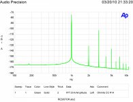
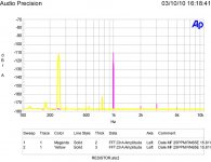
Three curves showing resistor distortion. Using my bridge technique the fundamental of 0 level is suppressed.
First a good Dale RN65 resistor, second an Ohmite 1/2 watt carbon composition type and finally the effect frequency has on another Dale.
On the CC resistor it is not just the added harmonics, note the base spreading which can be caused by an increase in 1/f noise.
On the third image notice how the third harmonic distortion increases as frequency decreases. Also not there is not much change in the second harmonic for a two octave change in frequency.
Attachments

Last edited:
Thanks. That's something I have suspected for a long time, but never had the time/resources/will to confirm.On the CC resistor it is not just the added harmonics, note the base spreading which can be caused by an increase in 1/f noise
When idle, all resistors are made equal, they just generate thermal noise, but when a carb-comp resistor is subjected to an AC signal, it generates an excess noise proportional to the instantaneous amplitude of the signal, smearing and widening the original spectral line.
Beautiful demonstration, also showing that crappy resistors and potentiometers have an influence extending on the signal further than just their basic non-linearity
Resistors surely do distort but mechanisms not well understood.
It is deeply understood.
Uncontaminated homogeneous low density carbon powder gives low distortion.
Symmetry is a meaningless term here.
The distortion measurement in post #76 is a joke.
The Chua paper is a piece of junk.
Many theories but nothing conclusive on conduction in bulk carbon.
I'm sticking with my statement that carbon conduction is not well understood.
I'm sticking with my statement that carbon conduction is not well understood.
It is deeply understood.
Uncontaminated homogeneous low density carbon powder gives low distortion.
Symmetry is a meaningless term here.
The distortion measurement in post #76 is a joke.
The Chua paper is a piece of junk.
And you are a troll, but what has that got to do with anything?
- Home
- Design & Build
- Parts
- What causes resistor distortion?