Nice summary. I'll make only two comments:
I understand the aim of transitioning from a waveguide - makes a lot of sense for smooth horizontal DI I suspect you are close to the limit for a passive solution, over the band.
Dipoles are picky about location, indeed. In my case the rear sound goes (roughly) into a corner about 2.1m away. There's over 10ms of delay before that sound reaches the listening area. Recognizing that such a location would be acceptable allowed me to try dipoles - if they had to be much nearer to the wall, I wouldn't have tried.
Ken
ps. having read your later post, I wouldn't use dipoles there.
Last edited:
It looks like the usable bandwidth is limited by the low frequency loss and not by ability to control the pattern. Some of the last measurements seemed to achieve < 100Hz pattern control like emulations suggested but I'm not sure if this is reliable data due to windowed measurements? By pattern control I mean the DI can be flat down to very low frequency although anything less than 200Hz with 8" driver requires quite lot of EQ so I see a 2-3 octaves of usable pattern control rule of thumb is valid.
The DI could be taken a bit higher by increasing path length difference from the front to aperture with some trickery, wings on the baffle corners or something. Unfortunately this would add some diffraction problems back. Moving back the ports wouldn't elongate the path length difference too much, wider front panel would be needed I think but then it is much harder to fabricate since roundovers are needed to negate diffraction interference. 8c uses wide baffle, ports are backed up from the front by similar distance and the woofer is attached back of the baffle. Both tricks increase path length on the front more than on the back wave. Anyway, I'll try with some other configurations at some point, it looks like better performance for my system is possible, at least I'm optimistic it is
The DI could be taken a bit higher by increasing path length difference from the front to aperture with some trickery, wings on the baffle corners or something. Unfortunately this would add some diffraction problems back. Moving back the ports wouldn't elongate the path length difference too much, wider front panel would be needed I think but then it is much harder to fabricate since roundovers are needed to negate diffraction interference. 8c uses wide baffle, ports are backed up from the front by similar distance and the woofer is attached back of the baffle. Both tricks increase path length on the front more than on the back wave. Anyway, I'll try with some other configurations at some point, it looks like better performance for my system is possible, at least I'm optimistic it is
Last edited:
Welcome back Don!
Very nice work as usual!
Thanks, more coming.
Great work DonVK!
I was contemplating on the idea of using an active cardioid, that has a fir filter on the back woofer.
It will be set up in such a way that introduces a variable delay with frequency.
Thus one should theoretically get directivity at more than 1 frequency band.
I'm not sure if it's been done before..
Thanks, the sub will be left off the next model. It does not really help the lower midrange.
DonVK impressive skills on the BEM software
Anyway, million things that would be nice to inspect
- effect of box depth
- effects of box volume / aperture size (acoustic low pass)
- effect of moving the apertures closer / further the front
- different baffle widths along with the aperture position
- effect of few different damping materials
- effect of the outside dimensions of the box (depth) without increasing volume inside
I have no idea how much work it would be, specialists job anyway.
Agreed, the subs are not helping (one variable now removed) so they get removed going forward. The questions will be answered (or investigated) once a working model is in place. It's getting close.
I agree, it would be more interesting to have a conceptual understanding of the relationships between the parameters rather than reverse engineering a commercial product on a public forum.
It would be great to those kinds of simulations if it suits DonVK and if it is not onerously time consuming.
Forgot to add, I think it is best to simulate the damping material using performance and density values of a commercial product so it can be easily replicated in real life for testing.
I'm starting with something that we know works in order to understand it. I'm not sure myself (at this time) what parts are important. It will eventually evolve to some design "rules of thumb". I have no plans to build a clone C8 clone, as my needs are different, but I would like to understand how this cardioid works.
Would you be able to plot some data of your past measurements on the impedance tube or perhaps make new ones?
It would be very nice to visualize both attenuation and delay the material adds against frequency on a graph. Seeing what the shape of the lines look like would help to better understand what is going on, what is the relation of the absorption coefficients to the delay. Delay is the only thing we need to control the pattern and needs to be rather specific, attenuation is the enemy and should be minimum, both happen when sound exists the box through the damping material.
I think most valuable tests on the tube would be some common ~3cm insulation as is and compressed maybe to half thickness to see how the compression affects the absorption / delay. Melamine sponge would be nice to see results of, worked fine in this application, better than 3cm insulation material as is. Some felt would be third material of my interest
About absorption and reflection: is there any rule of thumb here, what is the relation of the two? If absorption is 0.5, is the reflection then simply 1 - 0.5? Anyway, part of the sound stays in the box and part exists through the aperture and damping material.
I have hypothesis related to this: since the delay of the back wave needs to be rather specific to achieve narrow pattern (delay is the only thing that is needed to change the pattern), the sound should exit the box as fast as possible without bouncing around causing additional delay. If the reflection is high, part of the sound stays in the box and takes exit later. In this case the delay inside the damping material should be very low to allow this "leftover" sound delay due to reflection not to ruin the overall response (with too much delay). Do you think this is relevant issue?
If this is true then the relation of absorption and reflection of the material would determine max performance achieved by damping material alone. I mean, if less reflection is achieved by increasing absorption and the two are against each other. Additional delay lowers DI, as does additional attenuation, they need to be balanced. It might be the case that it is very difficult to get past 6dB DI because of the relation of delay and attenuation, unless there is material which has the balance between the two right that allows higher DI. Battle of the two properties, delay and attenuation and I think this is the biggest part of the problem in practice.
One can counteract the delay with path length difference of the front and back. What happens inside the box (back of the box) would matter as well, reflected sound could be attenuated and delayed (or not) before it tries another exit. I know the box I'm using is relatively small compared to wavelengths, I can't quite imagine how this all plays out, can it be assumed inside is mostly pressure and estimate some approximations how the sound exist the box over time?
Well, solving the relation of absorption and delay (speed of sound?) in the damping material to get more insight from the measurements. In general, too much delay seems to be too easy to do, keeping the DI on the low side. Anyway, more understanding what happens would help anyone to use pattern controlled mid in their projects.
Thanks a bunch!
Yes the wave is either absorbed or reflected (A+R=1) usually just the abs magnitudes are used because the coefficients are complex.
When I measure material for the port resistance I will post it. I'm thinking the resistive material be be used to lower a box "Q" or smooth things out.
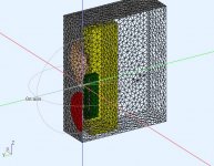
What's missing are the BEM observation fields showing pressure inside the box, ports and outside. They will be added when I'm closer. It's sometimes easier to see whats going on inside with them.
I'm not convinced the cancelling mechanism is reflection. The ports are beside the rear of the woofer. It seems that significant port output is required across a wider bandwidth and I don't think reflections are sufficient because the wavelength is quite large at these freq.
I'm hoping the concept is not that sensitive to physical placement of parts (fingers crossed) so there's some design latitude. That said, there is always an optimum.
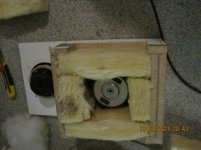
Did some changes on fiberglass stuffing. The waves is now crossing the fiber plates. See picture.
Attenunation at 90deg. is some better compared with post 182. DI is not impressive, but attenunation is now -8-10dB up to port working range about 450Hz.
Attenunation at 90deg. is some better compared with post 182. DI is not impressive, but attenunation is now -8-10dB up to port working range about 450Hz.
Attachments
DD C8 V2 - tuning changed
The model subwoofers have been removed as they do not contribute to the midrange DI improvement.
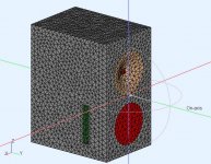
Changes in V2 model. The woofer chamber was reduced to 12L and the port depth is reduced to 40mm in an attempt to raise the box Q and increase port output. The woofer XO has increased to 150Hz to help soften the "Q" bump however some minor EQ is still required. I have added a quick tweeter conic waveguide as I was interested in matching DI at the XO so it can be ignored for now. There is still no resistive material in the port for this model.
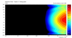
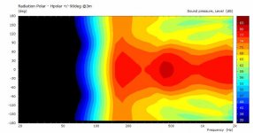
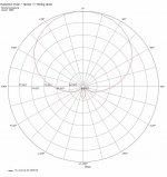
I think the model is now acting close enough to what I think is needed. In particular, there is enough port output, and the peaks/dips are close together to be able to smooth them (and add delay) with some resistive material in the port. The woofer will control its own DI >700HZ so we can acoustically close the ports @ >700Hz. That leaves resistive port requirement ~150Hz : ~700Hz. Using pic#8 it looks like 12dB difference between front and side/back at 500Hz.
Next model (V3) will have resistive material added to the ports. Then we can draw some conclusions about using it in a more generic way.
Pics 1,2 : BEM model
Pics 3 : woofer contribution
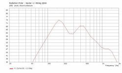
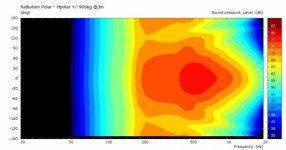
Pics 4,5 : port contribution, polar then speaker on axis response
Pics 6 : tweeter + WG contribution
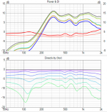
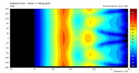
Pics 7 : all outputs combined
PIcs 8 : polar radiation pattern @500Hz
The model subwoofers have been removed as they do not contribute to the midrange DI improvement.
Changes in V2 model. The woofer chamber was reduced to 12L and the port depth is reduced to 40mm in an attempt to raise the box Q and increase port output. The woofer XO has increased to 150Hz to help soften the "Q" bump however some minor EQ is still required. I have added a quick tweeter conic waveguide as I was interested in matching DI at the XO so it can be ignored for now. There is still no resistive material in the port for this model.
I think the model is now acting close enough to what I think is needed. In particular, there is enough port output, and the peaks/dips are close together to be able to smooth them (and add delay) with some resistive material in the port. The woofer will control its own DI >700HZ so we can acoustically close the ports @ >700Hz. That leaves resistive port requirement ~150Hz : ~700Hz. Using pic#8 it looks like 12dB difference between front and side/back at 500Hz.
Next model (V3) will have resistive material added to the ports. Then we can draw some conclusions about using it in a more generic way.
Pics 1,2 : BEM model
Pics 3 : woofer contribution
Pics 4,5 : port contribution, polar then speaker on axis response
Pics 6 : tweeter + WG contribution
Pics 7 : all outputs combined
PIcs 8 : polar radiation pattern @500Hz
Attachments
-
 Port-output-on-axis.jpg41.6 KB · Views: 106
 -
 DD-C8-V2a-Tweeter-Contribution.jpg25.9 KB · Views: 105
 -
 DD-C8-V2-p1.jpg87 KB · Views: 257
 -
 DD-C8-V2-p2.jpg84.9 KB · Views: 252
 -
 DD-C8-V2a-Woofer-Contribution.jpg30.5 KB · Views: 251
 -
 DD-C8-V2a-Port-Contribution.jpg33.2 KB · Views: 115
 -
 DD-C8-V2a-All.jpg29.9 KB · Views: 120
 -
 DD-C8-V2-radiation pattern @500Hz.jpg73.3 KB · Views: 120
Last edited:
Alright, time for recap?
Following text is a think through, not too scientific, to help visualize what is going on in a system like this. At least this is what my understanding of it all is at the moment. All the following can be tested in the VituixCAD emulator, can't go deeper than that. I'm writing it in confidence although my experience on this is not too much, all written in this thread since few weeks and believe me this heavy post is the short simplified version. Ready?
In short, the pattern is achieved delaying the back side sound in comparison to the sound from the front and when the two meet at the port cancellation happens. No delay on the back results in dipole response. Start increasing the delay and you start turning the null from 90 degrees to the side to the back until after the various cardioid patterns the response widens to something omni. Some where in between is our target response.
To get sound to cancel the two needs to be in opposite phase, have similar frequency response and volume. We are trying to cancel sound at the side of a box, sound from the front and back of a cone on the next side of the box. If there was no box these would nicely cancel out, a dipole. We want nice cancellation but more at the back than at the side so a delay is needed to steer the null.
Sound from the front of the box is what diffracts around the corner so roughly wavelengths longer than the baffle width, the baffle step. For this reason some sort of attenuation of highs at the back is nice to roughly match the frequency responses at the port for good cancellation, right?
Lets set we have some filtering on the back, acoustic low pass filter would be all we need. Provides group delay and attenuation of the highs on the back wave. But since this is achieved with a box and apertures there is going to be reflections inside that could do with some damping.
Consequently acoustic low pass of the box and attenuation of the highs in the damping material both create (group) delay as well and it already starts to move the null a bit from the dipole position. From now on you need to be cautious with the delays.
So, the delay is going to accumulate on the back due various mechanisms at play. Damping material absorption coefficients rising with frequency, acoustic low passing of the back volume and ports, physical path length to the port and maybe some of the sound exiting a bit later due to reflections inside. Apparently sound velocity slows down in the damping material so count that in. Now, if the delay is perfect you get your response! But, the delay is probably is too much and the pattern got from dipole to super and hyper cardioid to something in the cardioidish territory. Lets think how the delays can be minimized to narrow the pattern to at least cardioid.
Each of the delays can be minimized like so.
- Acoustic low pass of the back volume and ports is moved up in frequency by reducing the volume of the box and increasing the port size.
- The absorption coefficients of most materials are low on the low frequencies and they rise at some point for the material to be effective at all. High absorption (attenuation) deteriorates the cancellation, this is fine with the high frequencies which are less from the front as well. Look for absorption coefficient graph line slope something like the baffle step perhaps? Anyway, look for small coefficients on the low end of the bandwidth you are trying to cardioid. Slope makes some group delay.
- Short physical path length form the back of the cone to the port is achieved when the port is just at the edge of the driver, tall and narrow.
- if the reflections matter, they should exit as fast as possible, kind of asks for small volume on the back.
- speed of sound in porous material, I don't have mucho info about this, I'd guess this is not too much with mild absorption we already had to minimize.
Now, lets imagine all of the delays were constant over frequency. If you got too few delay the pattern is something like dipole but attenuation might effect it some if there is damping material. If the delay is too much you are with something cardioidish with low DI.
To fix too few delay, to get the DI lower to your target, just use more damping material or different one with more absorption on the lows in general. Both attenuation and delays go up and the pattern widens. I like to imagine the absorption coefficients as shelving filter, lows aren't attenuated, then there is ramp up to high attenuation in high frequencies (-20dB magnitude). I think this is rarely the case unless used a napkin as damping material.
To fix too high delay on the back, which is there because you had to use certain damping materials and port sizes and box volume for various reasons, the delay can be compensated by increasing delay of the front wave as well. Delay of the front depends solely on the path length from the cone to the port around the corner. We have a square box and a port is on the side, the port is tied to both front and back path lengths. The distances to the port are roughly the sides and hypotenuse of right angle triangle so it is rather easy to approximate where the port needs to be. To increase the front distance more than the back distance use equal sided triangle as guide for maximal path length difference with smallest box Mind you, when the delay needs to be compensated by increasing path length to the front the baffle gets wider and the baffle step frequency lowers a bit which probably affects what the filters on the back should be doing, the box volume changes and what not. All of this which would increase the delay on the back making a vicious circle. For this reason the equal sided triangle port location should work best, less change to anything else than to the physical path length difference of front and back. Small changes might work just fine by moving the port back without widening the baffle, especially when one starts to think the physical distances more closely.
Core of all this is the damping material. If no suitable one is found, one could perhaps "tune" the damping material with compression. In general, less is better, thin acoustic materials should yield better response than heavy insulation.
In addition to matching the delay and frequency response at the port, the power needs to be roughly the same for good cancellation. If the back signal is attenuated the cancellation starts to deteriorate and pattern widens.
Then there is more, but I think this is the core of it.
I think there is not necessarily need to know the exact delays and corner frequencies and processes and what not. Performance of such box needs to be tested anyway with a prototype so I've been thinking this from the practical point of the view. You've got a driver, build small box for it and test few damping schemes. Move the ports if necessary.
ps. I still don't know what the acoustic resistance represents here? I don't know what it is, have I skipped it completely? It looks like every effect should be very minimal on the back wave to get a nice high flat DI pattern so I haven't been too worried about the resistance
Following text is a think through, not too scientific, to help visualize what is going on in a system like this. At least this is what my understanding of it all is at the moment. All the following can be tested in the VituixCAD emulator, can't go deeper than that. I'm writing it in confidence although my experience on this is not too much, all written in this thread since few weeks and believe me this heavy post is the short simplified version. Ready?
In short, the pattern is achieved delaying the back side sound in comparison to the sound from the front and when the two meet at the port cancellation happens. No delay on the back results in dipole response. Start increasing the delay and you start turning the null from 90 degrees to the side to the back until after the various cardioid patterns the response widens to something omni. Some where in between is our target response.
To get sound to cancel the two needs to be in opposite phase, have similar frequency response and volume. We are trying to cancel sound at the side of a box, sound from the front and back of a cone on the next side of the box. If there was no box these would nicely cancel out, a dipole. We want nice cancellation but more at the back than at the side so a delay is needed to steer the null.
Sound from the front of the box is what diffracts around the corner so roughly wavelengths longer than the baffle width, the baffle step. For this reason some sort of attenuation of highs at the back is nice to roughly match the frequency responses at the port for good cancellation, right?
Lets set we have some filtering on the back, acoustic low pass filter would be all we need. Provides group delay and attenuation of the highs on the back wave. But since this is achieved with a box and apertures there is going to be reflections inside that could do with some damping.
Consequently acoustic low pass of the box and attenuation of the highs in the damping material both create (group) delay as well and it already starts to move the null a bit from the dipole position. From now on you need to be cautious with the delays.
So, the delay is going to accumulate on the back due various mechanisms at play. Damping material absorption coefficients rising with frequency, acoustic low passing of the back volume and ports, physical path length to the port and maybe some of the sound exiting a bit later due to reflections inside. Apparently sound velocity slows down in the damping material so count that in. Now, if the delay is perfect you get your response! But, the delay is probably is too much and the pattern got from dipole to super and hyper cardioid to something in the cardioidish territory. Lets think how the delays can be minimized to narrow the pattern to at least cardioid.
Each of the delays can be minimized like so.
- Acoustic low pass of the back volume and ports is moved up in frequency by reducing the volume of the box and increasing the port size.
- The absorption coefficients of most materials are low on the low frequencies and they rise at some point for the material to be effective at all. High absorption (attenuation) deteriorates the cancellation, this is fine with the high frequencies which are less from the front as well. Look for absorption coefficient graph line slope something like the baffle step perhaps?
Anyway, look for small coefficients on the low end of the bandwidth you are trying to cardioid. Slope makes some group delay.- Short physical path length form the back of the cone to the port is achieved when the port is just at the edge of the driver, tall and narrow.
- if the reflections matter, they should exit as fast as possible, kind of asks for small volume on the back.
- speed of sound in porous material, I don't have mucho info about this, I'd guess this is not too much with mild absorption we already had to minimize.
Now, lets imagine all of the delays were constant over frequency. If you got too few delay the pattern is something like dipole but attenuation might effect it some if there is damping material. If the delay is too much you are with something cardioidish with low DI.
To fix too few delay, to get the DI lower to your target, just use more damping material or different one with more absorption on the lows in general. Both attenuation and delays go up and the pattern widens. I like to imagine the absorption coefficients as shelving filter, lows aren't attenuated, then there is ramp up to high attenuation in high frequencies (-20dB magnitude). I think this is rarely the case unless used a napkin as damping material.
To fix too high delay on the back, which is there because you had to use certain damping materials and port sizes and box volume for various reasons, the delay can be compensated by increasing delay of the front wave as well. Delay of the front depends solely on the path length from the cone to the port around the corner. We have a square box and a port is on the side, the port is tied to both front and back path lengths. The distances to the port are roughly the sides and hypotenuse of right angle triangle so it is rather easy to approximate where the port needs to be. To increase the front distance more than the back distance use equal sided triangle as guide for maximal path length difference with smallest box
Mind you, when the delay needs to be compensated by increasing path length to the front the baffle gets wider and the baffle step frequency lowers a bit which probably affects what the filters on the back should be doing, the box volume changes and what not. All of this which would increase the delay on the back making a vicious circle. For this reason the equal sided triangle port location should work best, less change to anything else than to the physical path length difference of front and back. Small changes might work just fine by moving the port back without widening the baffle, especially when one starts to think the physical distances more closely. Core of all this is the damping material. If no suitable one is found, one could perhaps "tune" the damping material with compression. In general, less is better, thin acoustic materials should yield better response than heavy insulation.
In addition to matching the delay and frequency response at the port, the power needs to be roughly the same for good cancellation. If the back signal is attenuated the cancellation starts to deteriorate and pattern widens.
Then there is more, but I think this is the core of it.
I think there is not necessarily need to know the exact delays and corner frequencies and processes and what not. Performance of such box needs to be tested anyway with a prototype so I've been thinking this from the practical point of the view. You've got a driver, build small box for it and test few damping schemes. Move the ports if necessary.
ps. I still don't know what the acoustic resistance represents here? I don't know what it is, have I skipped it completely? It looks like every effect should be very minimal on the back wave to get a nice high flat DI pattern so I haven't been too worried about the resistance
Last edited:
DonVK ...
The woofer XO has increased to 150Hz to help soften the "Q" bump however some minor EQ is still required.
Do you think it would be possible to augment the drooping lows with the Q bump? Can you raise it a bit higher in frequency still to the 150Hz region or above.
Hefty EQ boost is needed to get this low frequency output. Which is not that big of a deal in home SPL levels but if there is free output available in the system it should be exploited, unless it comes with worse trade-off.
Very cool data you can pull out with the BEM, if that doesn't help to get the ins and outs of passive cardioid mid system I don't know what
edit. read the text again, the box Q bump appears at the port only? this can't be exploited to boost the lows i think. It will limit the pattern control bandwidth above the Q frequency, right?
Last edited:
You can get a very nice response with just a 2nd order FIR filter and tune the delay to get the right pattern at the frequency range of interest. A low slope filter like that can be made to have about 10ms of latency which makes it almost real time playback capable. You could make a funky variable filter to extend the bandwidth but I'm not sure it's worth the effort.Great work DonVK!
I was contemplating on the idea of using an active cardioid, that has a fir filter on the back woofer.
It will be set up in such a way that introduces a variable delay with frequency.
Thus one should theoretically get directivity at more than 1 frequency band.
I'm not sure if it's been done before..
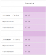
Kimmo has suggested that Hyper or super cardioid could be better patterns to aim for and they have higher theoretical DI.If you are looking for more DI, that wouldn't be "cardioid" and I don't see how it could result from a resistive material and provide constant directivity.
Here is a graph showing various theoretical DI's 1st order cardioid is the same as dipole 4.8 dB.
Interpreting the Directivity Index (DI) - The Hearing Review – a MEDQOR brand
Attachments
@fluid
Handy table, thanks, and for the link. It's a much better reference than I found.
1st order:
Those are the same numbers I'd found with 6dB as the limit. For cardioid, I rounded 4.8dB to 5dB.
2nd order:
Fine with DSP and a second radiator yielding 8dB DI, or so - that's something I might have tried to match a shallow waveguide.
In the passive/single-driver case, I don't see how to do get more than 6dB DI over more than about an octave. Is there a practicable single-driver solution that can work in the band of interest?
Ken
ps. and the link shows the calculation that I was too lazy to do yesterday...
Last edited:
kstrain, the vituixcad emulation suggests no problem achieving more than one octave as long as the delays are minimized. My prototype could test it, either reduce delay on the back even more and/or increase path length of the front wave. Real world test would show if it delivers or not I could enlarge the holes a bit to the back and shave some thickness of from the melamine and it should do it, not too much work other than setting up the measurement rig but I'm not sure when I have opportunity to take measurements.
I could enlarge the holes a bit to the back and shave some thickness of from the melamine and it should do it, not too much work other than setting up the measurement rig but I'm not sure when I have opportunity to take measurements.
Last edited:
I don't see how, a second order gradient is two dipoles being used in the same way two monopoles are used to form a first order cardioid.In the passive/single-driver case, I don't see how to do get more than 6dB DI over more than about an octave. Is there a practicable single-driver solution that can work in the band of interest?
Some information on them here
Second Order Gradients
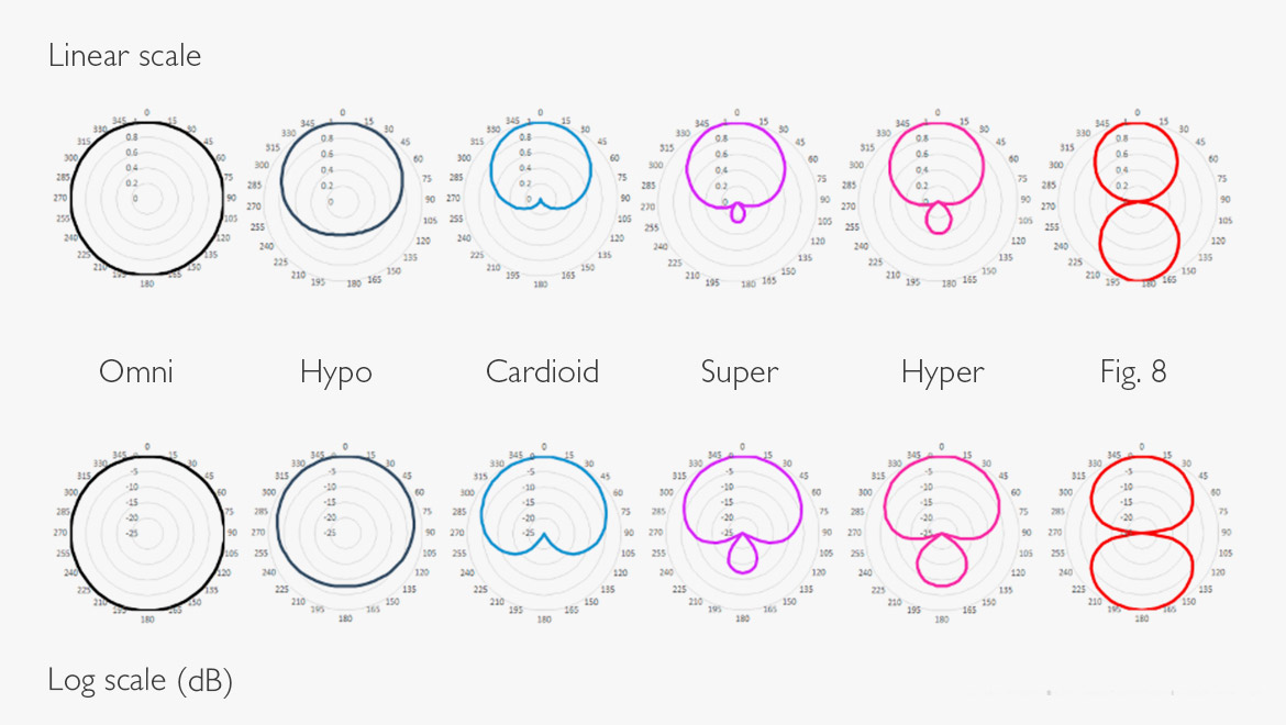
About directivity patterns and differences in frontal dispersion of cardioid vs. dipole etc, there seems to be some differencies in presented theoretical graphs, eg. dB scale can be lin or log.
Most likely real world measured patterns will never be ideal because of baffle and box (or microphone body). For loudspeaker design and simulation perhaps we should not be too demanding about these definitions?
I look at spl drop mostly at 30, 60 and 90 deg in frontal hemisphere. Backside patterns typically vary much more. Dipole pattern is narrover at 60deg than cardioid or supercardioid.
https://mhacoustics.com/sites/default/files/Beamformer Datasheet_R02A.pdf
Do Google search "directivity patterns"
Last edited:
As some of you are aware, I'm pursuing an active cardioid in this thread showing Vituix simulation results
https://www.diyaudio.com/forums/full-range/337956-range-line-array-wall-corner-placement-152.html#post6785298
Above 500 Hz, directivity is provided by waveguide plus rim drivers. Someone recently pointed out that waveguide is best cardioid within its pattern control range.
I posted directivity charts this morning showing I'm getting nearly 10 db suppression to the sides and 20 db to the back, if Vituix can be believed. Its a benchmark against which these sims can be compared. I would love to repeat them in ABEC.
I struggle with abec but I've got some basic competence. If I could see your script, Don, I could use it as a template for doing my sims in Abec, thanks. I've got a 12 core Ryzen machine on order for this purpose. It will be fanless and able to run as long as necessary without annoying me.
About directivity patterns and differences in frontal dispersion of cardioid vs. dipole etc, there seems to be some differencies in presented theoretical graphs, eg. dB scale can be lin or log.
Most likely real world measured patterns will never be ideal because of baffle and box (or microphone body). For loudspeaker design and simulation perhaps we should not be too demanding about these definitions?
I look at spl drop mostly at 30, 60 and 90 deg in frontal hemisphere. Backside patterns typically vary much more. Dipole pattern is narrover at 60deg than cardioid or supercardioid.
https://mhacoustics.com/sites/default/files/Beamformer Datasheet_R02A.pdf
Do Google search "directivity patterns"
Thanks for posting the directivity plots. There are a few ways to plot them and the shape depends on which is used (fixed range, data range). I've included the same graph I posted earlier in both formats.
I agree, and I'm just interested in "more out the front, less out the side and back". The precise shape is less important. It's enough just to try to shape it passively
Active would be another story.Attachments

Do you think it would be possible to augment the drooping lows with the Q bump? Can you raise it a bit higher in frequency still to the 150Hz region or above.
Hefty EQ boost is needed to get this low frequency output. Which is not that big of a deal in home SPL levels but if there is free output available in the system it should be exploited, unless it comes with worse trade-off.
Very cool data you can pull out with the BEM, if that doesn't help to get the ins and outs of passive cardioid mid system I don't know what
edit. read the text again, the box Q bump appears at the port only? this can't be exploited to boost the lows i think. It will limit the pattern control bandwidth above the Q frequency, right?
Agreed, if you still want to keep XO=100Hz you would need some boost, just like the sealed subwoofers. In this experiment the XO point can vary as I need to understand the mechanism. After its working properly we can try to adjust the range up/down or see what its sensitive to. So XO at 100Hz or 150Hz is less of an issue to me now. The difference might even be related to the driver I picked.
The reason I'm looking at the box Q is that it seems to be the only mechanism to get more port output. If its tuned too low (driver+volume+port) then the wavelength is long and the output will be approx in phase with the driver like a traditional BR tuning.
A reflection will appear as single inflection points (very narrow [+ve, -ve ] couplets ) so they don't have the bandwidth required. The BEM model has mild chamber damping to suppress them.
Velocity of sound through a fixed homogeneous medium (eq. air) depends on the medium but it's velocity is relatively constant and independent of frequency. Attenuation is dependent on frequency. This is how I see damping material. Electronic IIR filters have both delay and attenuation that are frequency dependent so they are not suitable models for damping material.
As some of you are aware, I'm pursuing an active cardioid in this thread showing Vituix simulation results
https://www.diyaudio.com/forums/full-range/337956-range-line-array-wall-corner-placement-152.html#post6785298
Above 500 Hz, directivity is provided by waveguide plus rim drivers. Someone recently pointed out that waveguide is best cardioid within its pattern control range.
I posted directivity charts this morning showing I'm getting nearly 10 db suppression to the sides and 20 db to the back, if Vituix can be believed. Its a benchmark against which these sims can be compared. I would love to repeat them in ABEC.
I struggle with abec but I've got some basic competence. If I could see your script, Don, I could use it as a template for doing my sims in Abec, thanks. I've got a 12 core Ryzen machine on order for this purpose. It will be fanless and able to run as long as necessary without annoying me.
I just had a look at your thread. I like the idea of active beam shaping as it has more flexibility than passive.
I get very good correlations between BEM models and what I've built and measured. VCAD seems very good but I've never used it.
Thanks for the offer but these models only take about 45min on a older i7-2700K PC. It looks like you have the right machine for Line Array models. If you need help with models, just ask, and it gets much easier after you do a few.
.
...
The reason I'm looking at the box Q is that it seems to be the only mechanism to get more port output. If its tuned too low (driver+volume+port) then the wavelength is long and the output will be approx in phase with the driver like a traditional BR tuning.
It is interesting we seem to approach the DUT from opposite perspectives, you are thinking through the bass box perspective and I've been thinking it from no box perspective, a naked dipole driver as starting point. I've been using big ports and minimal stuff in my experiments to have barely enough box to get the little delay needed for the response and accepted the bass is lost like in dipole configuration as the trade-off.
I've never thought of the box and ports in this application nothing more than an acoustic low pass. A dipole as a starting point is almost there, it has max output at the back, equal that of the front but opposite phase. All one needs to do to dipole to get the other patterns have some delay to steer the null past 90 degrees and not attenuate the output off the back to preserve the cancellation.
Anyway, different perspectives are good, I'll follow what you come up with since it is all new to the discussion so far I think!
A reflection will appear as single inflection points (very narrow [+ve, -ve ] couplets ) so they don't have the bandwidth required. The BEM model has mild chamber damping to suppress them.
Yeah, main motivator for me to try the leaky box was to get rid of all sort of boxy effects off from the mid driver response, reflections are not good thing here I think. With bass they can be used for advantage but on the mid driver I'm not so sure if there is any benefit. Dipole would have least problems in this regard, but I've read it doesn't work well positioned near wall. Have to try some day though.
Velocity of sound through a fixed homogeneous medium (eq. air) depends on the medium but it's velocity is relatively constant and independent of frequency. Attenuation is dependent on frequency. This is how I see damping material. Electronic IIR filters have both delay and attenuation that are frequency dependent so they are not suitable models for damping material.
I thought acoustic filters would have same effect as electrical, phase and frequency response are the same thing in different domain, but I'm not confident talking about phase and group delay and what not in this context. I have to admin I never had the a-ha moment with group delay
All I know the experiments have been working pretty nice so far with very rudimentary reasoning so I'm still avoiding studying the group delay until I have to, some day
Last edited:
- Home
- Loudspeakers
- Multi-Way
- Resistive port cardioid active speaker insipired by D&D 8C