That would be cool if you can measure and produce the data! I have no idea how to include something like that to VituixCAD though. Any data and insight would be welcome in any case 🙂
Wow, advanced stuff on your thread, nice! https://www.diyaudio.com/forums/multi-way/326926-modular-active-3-progress-34.html#post6641589 has fiberglass measurements attached, seems fine for this application being rather constant for the >200Hz and up bandwidth. Just need to find out how thick layer to use. Delay would be cool to have but attenuation looks like it is bad for the pattern but good for smoothing out reflections.
Does the impedance tube measurements tell the delay, is it in the data already? is it similarly "constant" as attenuation and how much? What happens with compression, does the delay and attenuation vary separately? Very interesting, thanks chiming in with real stuff!
Everything is included in the coefficients for a particular material and thickness. It's always a tradeoff, if the material is packed too dense you can get more reflection and less absorption.
I can create trial resistive port profiles for the BEM model (above) to get the response I want, then use the impedance tube to try to match that profile using real materials.
Last edited:
Great work DonVK!
I was contemplating on the idea of using an active cardioid, that has a fir filter on the back woofer.
It will be set up in such a way that introduces a variable delay with frequency.
Thus one should theoretically get directivity at more than 1 frequency band.
I'm not sure if it's been done before..
DonVK impressive skills on the BEM software 😀 while the 8c workings are as interesting as any I'd like to see more generic type BEM sims that investigate how the mid cardioid system works. I think the back woofers could be left out in this case, might improve simulation time?
Anyway, million things that would be nice to inspect 😀
- effect of box depth
- effects of box volume / aperture size (acoustic low pass)
- effect of moving the apertures closer / further the front
- different baffle widths along with the aperture position
- effect of few different damping materials
- effect of the outside dimensions of the box (depth) without increasing volume inside
I have no idea how much work it would be, specialists job anyway.
while the 8c workings are as interesting as any I'd like to see more generic type BEM sims that investigate how the mid cardioid system works. I think the back woofers could be left out in this case, might improve simulation time?
I agree, it would be more interesting to have a conceptual understanding of the relationships between the parameters rather than reverse engineering a commercial product on a public forum.
It would be great to those kinds of simulations if it suits DonVK and if it is not onerously time consuming.
Forgot to add, I think it is best to simulate the damping material using performance and density values of a commercial product so it can be easily replicated in real life for testing.
Last edited:
Everything is included in the coefficients for a particular material and thickness. It's always a tradeoff, if the material is packed too dense you can get more reflection and less absorption.
I can create trial resistive port profiles for the BEM model (above) to get the response I want, then use the impedance tube to try to match that profile using real materials.
Would you be able to plot some data of your past measurements on the impedance tube or perhaps make new ones?
It would be very nice to visualize both attenuation and delay the material adds against frequency on a graph. Seeing what the shape of the lines look like would help to better understand what is going on, what is the relation of the absorption coefficients to the delay. Delay is the only thing we need to control the pattern and needs to be rather specific, attenuation is the enemy and should be minimum, both happen when sound exists the box through the damping material.
I think most valuable tests on the tube would be some common ~3cm insulation as is and compressed maybe to half thickness to see how the compression affects the absorption / delay. Melamine sponge would be nice to see results of, worked fine in this application, better than 3cm insulation material as is. Some felt would be third material of my interest 🙂
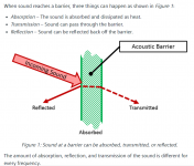
About absorption and reflection: is there any rule of thumb here, what is the relation of the two? If absorption is 0.5, is the reflection then simply 1 - 0.5? Anyway, part of the sound stays in the box and part exists through the aperture and damping material.
I have hypothesis related to this: since the delay of the back wave needs to be rather specific to achieve narrow pattern (delay is the only thing that is needed to change the pattern), the sound should exit the box as fast as possible without bouncing around causing additional delay. If the reflection is high, part of the sound stays in the box and takes exit later. In this case the delay inside the damping material should be very low to allow this "leftover" sound delay due to reflection not to ruin the overall response (with too much delay). Do you think this is relevant issue?
If this is true then the relation of absorption and reflection of the material would determine max performance achieved by damping material alone. I mean, if less reflection is achieved by increasing absorption and the two are against each other. Additional delay lowers DI, as does additional attenuation, they need to be balanced. It might be the case that it is very difficult to get past 6dB DI because of the relation of delay and attenuation, unless there is material which has the balance between the two right that allows higher DI. Battle of the two properties, delay and attenuation and I think this is the biggest part of the problem in practice.
One can counteract the delay with path length difference of the front and back. What happens inside the box (back of the box) would matter as well, reflected sound could be attenuated and delayed (or not) before it tries another exit. I know the box I'm using is relatively small compared to wavelengths, I can't quite imagine how this all plays out, can it be assumed inside is mostly pressure and estimate some approximations how the sound exist the box over time?
Well, solving the relation of absorption and delay (speed of sound?) in the damping material to get more insight from the measurements. In general, too much delay seems to be too easy to do, keeping the DI on the low side. Anyway, more understanding what happens would help anyone to use pattern controlled mid in their projects.
Thanks a bunch!
Last edited:
..
Forgot to add, I think it is best to simulate the damping material using performance and density values of a commercial product so it can be easily replicated in real life for testing.
Yes this is very important for the whole process. Only some materials have absorption coefficients published, and even then the data is kind of sparse, only few frequency points on ~200-2kHz bandwidth on most of the data I've seen. It would be very cool to have so much insight into the numbers suitable materials could be estimated by the available absorption coefficient numbers.
Using available commercial products with standardized properties is very relevant for the build process as well, any variation and the response varies between built units.
Great work DonVK!
I was contemplating on the idea of using an active cardioid, that has a fir filter on the back woofer.
It will be set up in such a way that introduces a variable delay with frequency.
Thus one should theoretically get directivity at more than 1 frequency band.
I'm not sure if it's been done before..
Not a Kii Three type of thing? I think someone mentioned this kind of setup some time ago on some thread on the forums, can't remember where it was so no quote. As I understood it the idea was to use identical drivers on front and back, the back driver is low passed and timing manipulated by FIR so that on the low mids there is pattern control and then at the bass the response goes omni resulting nice force cancellation setup. Anycase, you can use VituixCAD to sim what needs to be done to achieve the performance. Active solution should be easy to tune 🙂 I've got no experience on FIR so can't help, using the IIR filters only 😀
"Delay" is caused by:
- path length difference of the back and front to the aperture
- acoustic low pass filter(s)
- filter effect of the damping material (ramping up absorption coefficients)
- speed of sound in the material? is this constant over all frequencies?
- only part of the sound leaving the box immediately, and the rest a bit later after reflection or two.
What else? All these combined make the delay of the back wave to the aperture. Or is it phase? I'm already confused with the terminology 😀 Sound coming from the front needs to have specific delay to make the pattern, to cancel out with the back wave at the aperture.
Some of the phenomena listed above cause delay by phase shift, the filters. Some are constant delay like the path length difference. Is the speed of sound lowered in the damping material and does lower speed of sound mean constant delay to all frequencies?
Regarding the reflections that cause the sound to partially stay in the box and cause delay by this, they are mostly high frequencies or what? Again, relation of absorption and reflection, does the reflection vary with frequency like the absorption, highs are reflected less since they are absorbed more? Lows fully reflected? I guess not so the relation between absorption and reflection is so that both go towards zero at low frequencies, can't imagine the shape of the lines of reflection and delay inside the material on a graph yet though.
Many things at play, excuse me if it is all trivial to you who have studied acoustics. Absorption and reflection seems to be governed by single term, transmission, gotta read some 😀
Allright, relation of absorption to reflection seems to be α = 1 − |R|^2 for planewave. Just gotta figure out what all this means 😀 reading this https://people.ee.ethz.ch/~isistaff/courses/ak1/acoustics-absorption-reflection.pdf, ugh, too much info for one afternoon.
edit. nice photo to accompany my ramblings. Found it here Siemens DISW, lots of nice compact info on this! for example humidity changes absorption quite considerably... climate at home changes the polar pattern, not very convenient. Incident angle also affects the reflection, alright, one more variable to play with 😀
Attachments
Last edited:
Speed of sound in solid materials or water is higher than in air. This is not relevant to absorption I think, it is more about porosity and perhaps length of fibers.
Allright, playing with emulator says I could tighten the pattern of the prototype (higher DI) by compensating the delay due to the inner workings by elongating the path length outside of the box, like 8c does. Wider baffle and port a bit more back. This makes outside path length longer than the inside while keeping square box, also mounting the driver back of the baffle instead of front would make a bit difference here. Both are more difficult to manufacture, but might be necessary to do to narrow the response down.
Last edited:
Juhazi, I found this forum thread that let me believe speed of sound changes also in porous material but I haven't checked any of it yet.
Sound Speed In Porous Absorbers - Gearspace.com Could be considerable amount of delay, if thick material with slow speed of sound is used 🙂
Sound Speed In Porous Absorbers - Gearspace.com Could be considerable amount of delay, if thick material with slow speed of sound is used 🙂
Last edited:
Separate ideal and practical.
Ideal: resistance results in a first order low pass response, i.e., 1/f and -90 degrees.
With a given material, still ideal, more resistance requires greater thickness, hence results in more (group) delay associated with the resulting low-pass filter. If you think of the sound wave travelling down a pipe, a an ideal low-pass with the appropriate corner frequency represents an ideal resistive material - by which I mean there's no other phase change than the ideal 90 degrees.
Of course there is no such material, and the geometry is more complicated than a pipe. I *guess* much of the art in cardioid design is choosing and blending materials to approximate perfect resistance over the required band yet ending up with a practical, safe result and the rest is choosing a reasonable geometry that allows resistance to dominate, i.e., has it's resonances out of the important band.
Again starting ideally, the ports used to release the back wave, together with the cavity (box), 2nd order, low pass filter, with more or less of a peak at the resonant frequency, then 1/f^2 low pass and 180 degrees phase lag. Moving closer to ideal, the "more or less" depends on the shape of the cavity and of the ports which together determine loss and therefore damping - I guess this gets quite messy, though I've never tried to calculate it. As usual with ports, in the real case there will be a series of resonances due to reflections in the cavity.
I would think that you want to put the port resonances at high enough frequency such that the resistive damping strongly dominates the response over your chosen bandwidth, and with enough resistance that the port resonance is well damped (Q~0,5) and the parasitic resonances are also damped, to ease low-pass filtering. Picturing the magnitude response, you want the 1/f to start well below the port resonance, so that the response only turns over to 1/f^2 well above that resonance. Right?
With enough resistance to push the 1/f corner down below your band, the group delay due to ideal resistance is then the transit time in the damping material, represented by a 1/f low pass and modelled in addition to geometrical travel-time.
I'm sure I've missed practical details. If I were to try, I would use DSP and extra drivers to bypass all these acoustic-engineering details, but I can see why those with good practical skills would persist with the acoustic solution. Best of luck with your project.
Ken
Yep, I it fits my thinking that measured speed of sound when passing through porous material is lower than passing through solid or homogenous material. But how come...
Shortly read that thread and it was not clear to me where slowing down comes from - transition from medium to another, reflections, or what really - and what really counts positive here is the delay it makes!
Shortly read that thread and it was not clear to me where slowing down comes from - transition from medium to another, reflections, or what really - and what really counts positive here is the delay it makes!
...
With enough resistance to push the 1/f corner down below your band, the group delay due to ideal resistance is then the transit time in the damping material, represented by a 1/f low pass and modelled in addition to geometrical travel-time.
I'm sure I've missed practical details. If I were to try, I would use DSP and extra drivers to bypass all these acoustic-engineering details, but I can see why those with good practical skills would persist with the acoustic solution. Best of luck with your project.
Ken
Thanks for the input and cheer ups Ken! I must admit I don't fully understand what you've just said but it seems to make sense the little I think I understand 😀
Problem here, the part I've quoted, is that the attenuation in the material is bad for the response. Attenuation lowers the DI (wider) and I feel this is the part that makes all of this difficult. Need to have the material there to dampen the resonances of the cavity and ports and what not but it makes the response worse (lowers the DI) at the same time. It takes some brain power with a prototype to figure out what needs to be done and what is achievable. Might be so that the 8c is the sweet spot, highest flattest DI achievable passively without problems with all the reflections and resonances, a good balance and DI happens to be what it is?
Surely the proto box I've built works perfectly nice already with DI almost 6dB with noticeable effect on directivity, it is small and sounds good without extra resonances and the bandwidth is about the same I had with a closed box before (in 3 way system). The directivity control is just a plus for the multiple other advantages like very easy woodwork, no diffraction problems, not much resonances, did I mention size? So box like this can be very good value for suitable project. But, if the pattern control is the main design goal I agree that active solution would yield better results and be very easy to tune, especially if DI needs to be above about 6dB. Active solutions come with extra (money) cost and bigger size so every project should choose solution that makes a better overall system in the end.
ps. I have few questions if you don't mind?🙂
How to determine port resonance Q, can you give some practical example?
What the acoustic resistance is in your post, is it delay (real part of acoustic impedance??) or contain other effects besides the delay like attenuation? I find it very difficult to imagine the acoustic resistance for some reason, I read the word as attenuation of sorts but don't know what it actually means.
Last edited:

Yep, I it fits my thinking that measured speed of sound when passing through porous material is lower than passing through solid or homogenous material. But how come...
Shortly read that thread and it was not clear to me where slowing down comes from - transition from medium to another, reflections, or what really - and what really counts positive here is the delay it makes!
At least there was some adiabatic / isothermal stuff mentioned. I bet there are some studies on what happens, didn't look for them yet.
Last edited:
Some of your plots, e.g., the 6th in #277, show close to cardioid response over about a decade in frequency, judged by suppression beyond +/- 135 degrees or the "orange" at +/-90 degrees, which is close to where it should be, if I'm judging the color correctly.
If you are looking for more DI, that wouldn't be "cardioid" and I don't see how it could result from a resistive material and provide constant directivity.
A couple of months ago, before embarking on a dipole project, I briefly wondered about cardioid, but decided to gamble on less radiation to the sides instead. That was based on a few concerns, mainly room dependent.
Ken
ps. I looked up DI for cardioid mics, and find a few sources suggesting 5dB - I didn't try to calculate it.
Last edited:
Ugh, lost lenghty response to power cut.
In short: yes the response is pretty good now, gotta be happy.
I've been talking the pattern names with -ish postfix since the actual name is not very important for practical application. I've got the speakers near wall and toed in 45 degrees so best location for deepest null for least reflections would be somewhere between 90 - 135 degrees.
Dipole response with nulls at 90 degrees has zero attenuation and delay on the back signal and to widen this a bit to hypercardioidish, move the null > 90 degrees, we need a little delay on the back signal but not much. Too much delay (or attenuation) and the response gets wide pretty fast. Cardioidish seems to be pretty easy to get but hypercardioidish I'm not so sure.
It is possible to steer the null in the emulation anywhere from 90 to 180 degrees at will by tuning the delay of the back wave. Hence the attempt to achieve DI > 6dB.
Another advantage of higher DI would be to achieve constant directivity with a waveguide. Most waveguides are about 100 degrees nominal dispersion or less. 8c seems to have waveguide something above 100 degrees. I'm using 80x60 tractrix horn (faital STH100) currently and the system DI is rising, about 8dB where the crossover happens. I'm happy with it but the DI is not constant which would be nice to try out if it is worth the trouble. Exchange to a wider pattern CD waveguide and narrow the cardioid mid pattern a bit and bam, constant directivity to Schroeder 🙂
So, it could yield better performance for a given system if we were able to adjust the pattern at will, get the DI above 6dB.
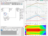
Attached emulation example is simplified ideal model of the bigger measured box with only "acoustic low pass" applied to the back side signal to provide some delay along with approximation of the path lengths in and outside the box. The example is ignoring all other effects like the damping material. The response has DI about 7dB, null ~-25dB is at 120 degrees, 180 degrees is about -10dB down. Nominal dispersion is about ~100 degrees which is off the shelf waveguide territory. This would have about 10dB less sound to the first reflection on the frontwall than the prototype with DI a bit shy of 6dB, quite a difference in numbers, not sure how different it would be in reality 🙂
I can manipulate the null angle easily in the emulation. Null changes with acoustic low pass fc, path length difference between the in / outside, and approximation of absorption coefficients ( shelving filter ) and attenuation. Not every phenomenon can be emulated in the VituixCAD with my skills, and not all emulation settings are possible in reality. Emulation was posted around post #233 if you want to try. Change the side port emulating drivers in series configuration, the configuration in the project file is wrong I think.
ps. Never tried dipoles, I read they don't work as well near the wall. Might give a try some day.
In short: yes the response is pretty good now, gotta be happy.
I've been talking the pattern names with -ish postfix since the actual name is not very important for practical application. I've got the speakers near wall and toed in 45 degrees so best location for deepest null for least reflections would be somewhere between 90 - 135 degrees.
Dipole response with nulls at 90 degrees has zero attenuation and delay on the back signal and to widen this a bit to hypercardioidish, move the null > 90 degrees, we need a little delay on the back signal but not much. Too much delay (or attenuation) and the response gets wide pretty fast. Cardioidish seems to be pretty easy to get but hypercardioidish I'm not so sure.
It is possible to steer the null in the emulation anywhere from 90 to 180 degrees at will by tuning the delay of the back wave. Hence the attempt to achieve DI > 6dB.
Another advantage of higher DI would be to achieve constant directivity with a waveguide. Most waveguides are about 100 degrees nominal dispersion or less. 8c seems to have waveguide something above 100 degrees. I'm using 80x60 tractrix horn (faital STH100) currently and the system DI is rising, about 8dB where the crossover happens. I'm happy with it but the DI is not constant which would be nice to try out if it is worth the trouble. Exchange to a wider pattern CD waveguide and narrow the cardioid mid pattern a bit and bam, constant directivity to Schroeder 🙂
So, it could yield better performance for a given system if we were able to adjust the pattern at will, get the DI above 6dB.
Attached emulation example is simplified ideal model of the bigger measured box with only "acoustic low pass" applied to the back side signal to provide some delay along with approximation of the path lengths in and outside the box. The example is ignoring all other effects like the damping material. The response has DI about 7dB, null ~-25dB is at 120 degrees, 180 degrees is about -10dB down. Nominal dispersion is about ~100 degrees which is off the shelf waveguide territory. This would have about 10dB less sound to the first reflection on the frontwall than the prototype with DI a bit shy of 6dB, quite a difference in numbers, not sure how different it would be in reality 🙂
I can manipulate the null angle easily in the emulation. Null changes with acoustic low pass fc, path length difference between the in / outside, and approximation of absorption coefficients ( shelving filter ) and attenuation. Not every phenomenon can be emulated in the VituixCAD with my skills, and not all emulation settings are possible in reality. Emulation was posted around post #233 if you want to try. Change the side port emulating drivers in series configuration, the configuration in the project file is wrong I think.
ps. Never tried dipoles, I read they don't work as well near the wall. Might give a try some day.
Attachments
Last edited:
Uh, missing crucial info from the post and edit time is over, must have deleted a paragraph accidentally.
I've got speakers up against the front wall and I'm using 45 degree toe in for wide sweetspot (altough listening to mono, hehe). DI anything above 6dB would reduce the first reflection from front wall a lot. Currently, the sound to first reflection point ~120 degrees is ~12dB down which is already nice but DI of about 7 would make this 10dB less. Lots of better in numbers, but not sure if this was that much more better in reality, the effect of pattern is noticeable already.
I've got speakers up against the front wall and I'm using 45 degree toe in for wide sweetspot (altough listening to mono, hehe). DI anything above 6dB would reduce the first reflection from front wall a lot. Currently, the sound to first reflection point ~120 degrees is ~12dB down which is already nice but DI of about 7 would make this 10dB less. Lots of better in numbers, but not sure if this was that much more better in reality, the effect of pattern is noticeable already.
- Home
- Loudspeakers
- Multi-Way
- Resistive port cardioid active speaker insipired by D&D 8C