At least the wife does not have to pull me out of bars.😀
LOL ... I hear that. I was lucky with my Ex, she would sit for hours listening with me and on a couple of occasions came up with some really good suggestions. Sadly, that is the only thing I miss about her.
Here is something that's surprised me.
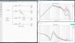
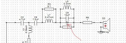
I thought I'd complete the notch filter comparison that Douglas did in post #23 by adding the tanking capacitor/inductor combination. To do this I had to add in a series inductor and considered it fair to add it in to all the other filters as well. Kind of closer to what is actually happening in the xo we are working on. Interestingly, it changed the results considerably.
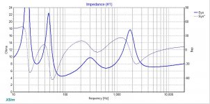
The differences in current consumption are completely different. The notch filter that now produces the highest current consumption is the 3rd example, the parallel notch which previously looked to be the best choice. The series notch in blue is having no effect on the current at the notch frequency but drawing more down around 200Hz. The tanking notch is increasing the current draw above the notch frequency but not to as high a value as the red, parallel notch filter.
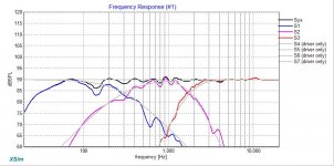
The differences in the FR to each filter are interesting to note as well. The red and green notches (parallel and tanking) tend to raise the response above the notch frequency. The series notch does this to a lesser extent and also increases the roll-off. That might actually be of some use. Achieving this double function while not raising the current draw at the notch frequency made me want to look at it more closely and see what it does in the actual full xo.
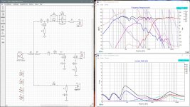
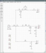
To that end, in the next pic I got rid of the tanking filter and added the series notch filter and with the added roll-off that it provides was able to also get rid of the 2nd order shunt capacitor. So now I've just got a 1st order HP and LP on the mid. Current draw actually looks to be improved over my 1st version. The FR isn't quite as smooth this time but should be acceptable and with a few other small changes in values here and there (for eg I switched from a series notch on the tweeter to a parallel one) the phase alignment is a bit improved.
Interesting.
I thought I'd complete the notch filter comparison that Douglas did in post #23 by adding the tanking capacitor/inductor combination. To do this I had to add in a series inductor and considered it fair to add it in to all the other filters as well. Kind of closer to what is actually happening in the xo we are working on. Interestingly, it changed the results considerably.
The differences in current consumption are completely different. The notch filter that now produces the highest current consumption is the 3rd example, the parallel notch which previously looked to be the best choice. The series notch in blue is having no effect on the current at the notch frequency but drawing more down around 200Hz. The tanking notch is increasing the current draw above the notch frequency but not to as high a value as the red, parallel notch filter.
The differences in the FR to each filter are interesting to note as well. The red and green notches (parallel and tanking) tend to raise the response above the notch frequency. The series notch does this to a lesser extent and also increases the roll-off. That might actually be of some use. Achieving this double function while not raising the current draw at the notch frequency made me want to look at it more closely and see what it does in the actual full xo.
To that end, in the next pic I got rid of the tanking filter and added the series notch filter and with the added roll-off that it provides was able to also get rid of the 2nd order shunt capacitor. So now I've just got a 1st order HP and LP on the mid. Current draw actually looks to be improved over my 1st version. The FR isn't quite as smooth this time but should be acceptable and with a few other small changes in values here and there (for eg I switched from a series notch on the tweeter to a parallel one) the phase alignment is a bit improved.
Interesting.
Attachments
Here is something that's surprised me.
...
Interesting.
It's one of those "why doesn't this work" things that many engineers run into all the time ... when you incorporate two filters back to back, they are going to interact in some very surprising ways.
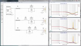
For example in your 3rd test, as soon as you added L3 it became part of the overall filter, changing it's resonant frequency and current behaviours.
Bear in mind that when a "tank" circuit resonates, the currents in the individual components can be, and often are, greater than the input current to the overall circuit. This is not magic, it is the resonant circuit storing energy and reacting in an exaggerated manner... which is, in fact, what we are counting on. (That was the ringing problem we talked about earlier.)
In a bandpass circuit we count on the circulating currents to significantly reduce the impedance, causing it to conduct more heavily. Perhaps even appearing to be shorted.
In a bandstop circuit we count on the circulating currents to increase the the filter's impedance, making it appear more like an open circuit.
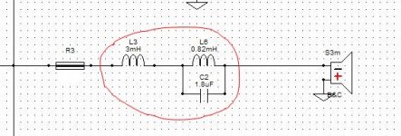
However; when you added the new coil which is much larger than the coil in the inline band stop filter you inadvertantly changed that circuit to a an inline band pass filter compirsed of L3 and c2... L6 will continue to have a minor effect on the circuit, increasing the sharpness of the resonance. Hence both a decrease and increase in input current at resonance as shown in the graphs below. The actual component currents are confined to the tank circuit itself which is why you don't see them on the inputs.
Also note that moving the new coil behind the tank circuit does not save you.
Interesting yes ... but completely explainable.
Attachments
Last edited:
Thanks jReave,
I appreciate your efforts in coming up with a workable crossover in place that exhibits good efficiency, frequency response, and phase alignment.😀 The tweeter certainly seems like the most difficult filter to design. If its okay with you I will give this one a try. I could sit at my computer the remainder of the year and not come up with anything that rivals your design.😀
Again Much Thanks,
Rich
Thanks jReave,
I appreciate your efforts in coming up with a workable crossover in place that exhibits good efficiency, frequency response, and phase alignment.😀
Ummm ... please note there might be a mistake in his design. The bandstop tank in his tweeter appears to be shorted...
Attachments
@Douglas Blake,
I will hold off until we get that sorted out. It probably will require another Parts Express order once we get something to test out. Hope your day is going well.😀
Best,
Rich
I will hold off until we get that sorted out. It probably will require another Parts Express order once we get something to test out. Hope your day is going well.😀
Best,
Rich
Montana, of course. Have at 'er. But don't discount what you are putting together. You have some good stuff there and your grasp of things has progressed well out of the beginner stage you were in a couple of years ago.
Also re measurements, if you haven't done so lately go back and read Bagby's measuring tutorial. I'm pretty sure I linked to it before for you but here it is again for any others.
Box
Of note - you don't have to be so far away for the farfield. Twenty inches may do just fine. Nor do you necessarily need a big open room. What matters is the gating you need to use, 4 or 5 msec. Consider this. Since sound travels about 1130ft/sec, in 4 msec it will only travel about 4.5ft. That means that if there are objects nearby that have a longer reflection path length of 4.5', they will not appear in your measurement. That's it. That's the condition you need to simply satisfy in order to get good far field measurements with that small of a gating window.
For nearfield, with a 9" cone, you can be as close as 1/2" from the dustcone. Then splice them together.
Douglas, thank you for that explanation. To be honest though, for someone like myself, despite years now working with speaker and xo design, without the electrical background a lot of that went over my head. But your charts helped me to see that you are getting different current readings when looking at the series resistors (which is what I did) vs the inductor and capacitor components. I'll run through those again for myself later and see if I can make more sense out of it.
Cheers
@Douglas Blake,
I will hold off until we get that sorted out. It probably will require another Parts Express order once we get something to test out.
@jreave is doing a pretty good job. His design is more complex than I would usually encourage but it looks like you've got some really gnarly drivers to work with. I'm sure it's just a drawing error.
Hope your day is going well.😀
So far...
I hope my circuit critiques are giving you the extra info you wanted... If you have crossover questions of a more general nature I'll be happy to try to answer them...
Douglas, thank you for that explanation. To be honest though, for someone like myself, despite years now working with speaker and xo design, without the electrical background a lot of that went over my head.
There is actually a pretty good explanation HERE , with more detail than a simple forum post can provide.
We can also explore it more on here, if you like.
The take away when messing with LC circuits is "Don't be surprised if they surprise you."
Last edited:
Douglas, you have a very good eye.
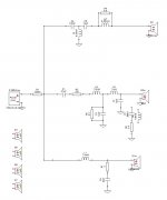
I threw that short in there to make a comparison and then forgot about it. The summed FR doesn't include that notch so I guess it doesn't actually need it. Huh. That's a nice surprise.
Just for clarity's sake, attached is the same xo schematic again but corrected this time. Everything else is the same as last time.
Attachments
Douglas, you have a very good eye.
😀 People have accused me of far worse.
Well, you noticed I refrained from saying anything about the other one! 😀
If you mean the ringing cap in the other circuit ... yes it did take me a while to suss that out. The reason I was concerned is that it appeared to be an accidental effect and it might have been audible...
If that's not what you meant... ????
No. Two eyes. I only mentioned one. Too subtle. Not everyone gets my sense of humor in person, let alone thru thus thingy. <shrug>
I could not help myself. So, I took another stab at a crossover design using ideas from jReave's schematic and some of my own. Please keep in mind that part of my goal is to utilize components that I already have on hand. As, @Douglas Blake point out it would be unwise to spend big on parts at this stage in the design process. Also, I'm viewing this as a learning experience.
Btw, the pic of current is with amp kicked up to 60 watts. I don't play anything at insane levels so I thought this would be a good level to use.
Best Regards,
Rich
Btw, the pic of current is with amp kicked up to 60 watts. I don't play anything at insane levels so I thought this would be a good level to use.
Best Regards,
Rich
Attachments

No. Two eyes. I only mentioned one. Too subtle. Not everyone gets my sense of humor in person, let alone thru thus thingy. <shrug>
Ahhh ... got it... Now it's funny! 🙄
I run into the same problem... my sense of humour, which is largely based on saying the worst possible thing at any given moment, doesn't always come across as humour... But hey, I always think it's funny.
Btw, the pic of current is with amp kicked up to 60 watts. I don't play anything at insane levels so I thought this would be a good level to use.
Perhaps I should clarify why I do that... it's the same as switching a meter or scope to a different scale. Testing equipment is always most accurate near full scale... so when something is small, you jack it up to get more "scale" out of it.
Turning up the amplifier power is not about the actual amplifier you are using ... if you notice all XSim does with that is to move things up scale, it does not produce different curves and it won't tell you "well you killed that driver"... So my only reason for jacking up the amplifier is to get more "scale" on the current and power graphs.
IF the current panel had scales that were useful at the standard 1 watt design level, I would use them instead.
To the creators of that software I would suggest that 500ma, 250ma and 125ma scales would be extremely useful.
Anyhow... this latest design looks pretty decent. Congrats.
There is one final exercise I do before going "Eureka" and waking all my neighbours (because it's 4:00am and I just had to finish) is to experimentally remove as many parts as I can without significantly degrading the performance...
Our ears and our rooms are very broad strokes devices, a couple of 1% differences, no matter how carefully achieved won't likely be noticed in the final rendering and common wisdom does suggest that as complexity approaches infinity failure approaches certainty.
Last edited:
montana1, I started thinking about the bass. Original Tarkus has sealed box, and that's what SLS 10" woofer is designed for. Tarkus - undefinition
But you seem to have BR tuning at around 30Hz. Have you done simulations of box volume and tuning? It takes a pretty long port...This sounds doable however, in LLT subwoofer style (Large Low Tuned) Anyway, my experience tells that sealed box bass is best for rock, best drum attack you know...
But you seem to have BR tuning at around 30Hz. Have you done simulations of box volume and tuning? It takes a pretty long port...This sounds doable however, in LLT subwoofer style (Large Low Tuned) Anyway, my experience tells that sealed box bass is best for rock, best drum attack you know...
@Juhazi,
It seems like somewhere than Paul Carmody changed his mind and went with a ported design. There was a discussion on this subject on Parts Express tech talk forum. If I remember right he wanted the max power handling possible since it was intended to be a Rock n' Roll speaker. With that said, I thought about making it a sealed cab all away along. It would be easy enough to stuff the ports. I even have near with near field measurements with ports sealed off. So, I am definitely thinking about going sealed at some point.😀
Best,
Rich
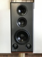
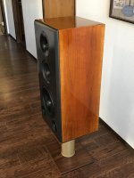
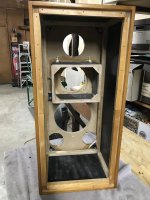
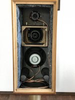
Hi Guys,
I wanted to post some photos of the actual speaker we have been designing the crossover for. I would like to mention that this cabinet design is patterned after the BBC approach of a thin well damped panels. So, I used 1/2" Baltic birch plywood veneered in Cherry than applied garnet shellac in french polish method (or a variation of it).😀 All inside panels were then lined with 1/8" thick mass loaded vinyl. I have built the heavy well braced speakers that require a hand truck to move around and I wanted to go a different route with this build.😀
This is only my 4th speaker build so don't judge it to harshly. I do think my speaker building has improved some. But, it's probably time to invest in a table saw.🙂
Best Regards,
Rich
Attachments
- Home
- Loudspeakers
- Multi-Way
- Xsim Critique- taking it to the next level