I'm just getting started with Xsim so signing on to this thread to follow. Have enjoyed reading so far.
Rich, we're not very far apart. Who knows, maybe some day we can get together and compare notes. I'm more of a tube amp building than a speaker builder but I've built a few and I have friends from my old audio club that are very experienced. Wish I still liver near them.
John
Rich, we're not very far apart. Who knows, maybe some day we can get together and compare notes. I'm more of a tube amp building than a speaker builder but I've built a few and I have friends from my old audio club that are very experienced. Wish I still liver near them.
John
I'm just getting started with Xsim so signing on to this thread to follow. Have enjoyed reading so far.
Thanks for chiming in. The thread was started to talk about some basic theory, efficiency and XSim tricks... There's a fair pool of wisdom here, so if you have questions...
@nerdorama
Absolutely, once this crisis is passed and work slows down let’s try to get together. I’m very much a newbie at this but making some progress. Glad you are following along with this thread. Hopefully it can keep on going even beyond my current project.😀
Best,
Rich
Absolutely, once this crisis is passed and work slows down let’s try to get together. I’m very much a newbie at this but making some progress. Glad you are following along with this thread. Hopefully it can keep on going even beyond my current project.😀
Best,
Rich
Howdy Rich,
I find your speakers quite interesting and good looking. I know how much a plain photo can do unjustice to them. I am hoping to start a build based on wg300 this year, somewhere late autumn, God willing.
I find your speakers quite interesting and good looking. I know how much a plain photo can do unjustice to them. I am hoping to start a build based on wg300 this year, somewhere late autumn, God willing.
So the one thing I'm worried about in the cabinet is the stand. It's going to rock against the woofer motion. When you get it working, you'll need to add weight to the bass and/or rigidity to the pillar.
Rich,
Very nice work on the final xo. You are hitting the target curves just about as good as you possibly can. And that takes just a bit of time fiddling with values back and forth until it feels like sometimes your eyes are about to pop out of your skull. Whittling things down and simplifying while still keeping to your targets is exactly what I was going to do next but you beat me to it. Nice.
Nice work on the build too. Looks very good. I will be interested in what you have to say about that style of cabinet as I tend to lean more towards the overkill end of the spectrum.
Now since this thread has learning as a theme, I wanted to just touch on a couple of further things in the xo.
Originally I wrote that with a mid in a 3-way with such a high impedance peak at resonance (close to 100 ohms I think), an impedance compensating filter was going to be essential. And yet Rich has opted not to use one while still avoiding any peaking in the mid's FR at its 100Hz resonance. How did he do this?
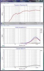
Pic 1 below shows the effect of the 47uF series HP capacitor on the FR in black. That's the ugly peak that results at about 100Hz. Adding an impedance compensating filter solves the problem (pink trace) but look at the values required. Not inexpensive. Now let's look at Rich's very elegant solution. He has combined a single resistor in parallel with the 1st shunt capacitor in the 4th order LP filter. The result in blue is that the resonance peak is taken care of, the response is actually also flattened out meaning you need to ask less of the rest of the LP components and the overall level is attenuated as well. That's 3 functions in just 1 resistor for a buck or two. That is perhaps one of the most efficient uses of a single component I have ever seen in a xo filter. Very, very nice.
The other problem Rich had was his waveguide tweeter response which had an ugly rising response after the HP filter was added (pic 2, black trace). One way to solve this is to add in a shunt capacitor which will act as a LP filter dropping the rising response (blue trace). The other option was an LR parallel combination in series with the tweeter which works as a shelving LP filter. It solves the rising FR problem nicely while at the same time also attenuating the small peaking that was still present around 2800Hz (red trace). That flattens the response out just about perfectly. Which one is better will depend on what the FR looks like to begin with.
However, we should note that those 2 options have different electrical results. In the case of the capacitor, the result is a current draw that is rising steeply in the HF's. In this case I'm giving it 50W and if that's all that the ampflifier can produce, its maximum current is going to be 3.5 amps into 4 ohms which will in fact be exceeded. A 100W amp minimum with 5 amps od current available into 4 ohms will be required.
On the other hand, the LR filter has no current draw problems but the resistor sees a whole heck of a lot of power running through it, about 30W when we are feeding the speaker as a whole with 50W. In contrast to the usual statements that a tweeter filter won't see that much power, here you are going to have to make sure that this resistor can handle this high wattage. Adding resistors together in parallel to get the correct value will do the trick if a single high wattage one can't be found. How high the wattage rating needs to be will depend on how much power you actually think you will be using.
Very nice work on the final xo. You are hitting the target curves just about as good as you possibly can. And that takes just a bit of time fiddling with values back and forth until it feels like sometimes your eyes are about to pop out of your skull. Whittling things down and simplifying while still keeping to your targets is exactly what I was going to do next but you beat me to it. Nice.
Nice work on the build too. Looks very good. I will be interested in what you have to say about that style of cabinet as I tend to lean more towards the overkill end of the spectrum.
Now since this thread has learning as a theme, I wanted to just touch on a couple of further things in the xo.
Originally I wrote that with a mid in a 3-way with such a high impedance peak at resonance (close to 100 ohms I think), an impedance compensating filter was going to be essential. And yet Rich has opted not to use one while still avoiding any peaking in the mid's FR at its 100Hz resonance. How did he do this?
Pic 1 below shows the effect of the 47uF series HP capacitor on the FR in black. That's the ugly peak that results at about 100Hz. Adding an impedance compensating filter solves the problem (pink trace) but look at the values required. Not inexpensive. Now let's look at Rich's very elegant solution. He has combined a single resistor in parallel with the 1st shunt capacitor in the 4th order LP filter. The result in blue is that the resonance peak is taken care of, the response is actually also flattened out meaning you need to ask less of the rest of the LP components and the overall level is attenuated as well. That's 3 functions in just 1 resistor for a buck or two. That is perhaps one of the most efficient uses of a single component I have ever seen in a xo filter. Very, very nice.
The other problem Rich had was his waveguide tweeter response which had an ugly rising response after the HP filter was added (pic 2, black trace). One way to solve this is to add in a shunt capacitor which will act as a LP filter dropping the rising response (blue trace). The other option was an LR parallel combination in series with the tweeter which works as a shelving LP filter. It solves the rising FR problem nicely while at the same time also attenuating the small peaking that was still present around 2800Hz (red trace). That flattens the response out just about perfectly. Which one is better will depend on what the FR looks like to begin with.
However, we should note that those 2 options have different electrical results. In the case of the capacitor, the result is a current draw that is rising steeply in the HF's. In this case I'm giving it 50W and if that's all that the ampflifier can produce, its maximum current is going to be 3.5 amps into 4 ohms which will in fact be exceeded. A 100W amp minimum with 5 amps od current available into 4 ohms will be required.
On the other hand, the LR filter has no current draw problems but the resistor sees a whole heck of a lot of power running through it, about 30W when we are feeding the speaker as a whole with 50W. In contrast to the usual statements that a tweeter filter won't see that much power, here you are going to have to make sure that this resistor can handle this high wattage. Adding resistors together in parallel to get the correct value will do the trick if a single high wattage one can't be found. How high the wattage rating needs to be will depend on how much power you actually think you will be using.
Attachments
Excellent analysis ...
But have you considered the solution below?
What that is a band stop filter tuned above 20khz so that the rising tweeter response falls into the edge of the resonant curve. Increasing response minus increasing impedance == corrected response.
Done properly it reduces amplifier loading quite nicely.
Depending on the reactance of the tweeter itself you may not even need the capacitor
Attachments
Last edited:
@Lojzek,
Glad to hear from you. Thanks for the compliment. I hope to be starting another build in autumn myself. Have fun with your build.😀
@eriksquires,
The speaker stand you see was only used for taking a few photos. New stands will be made for these speakers. Although, they are very heavy since the middle pvc pipe is filled with concrete.
@jReave,
All I can say is you and Douglas Blake set the bar very high.😀 When I started this thread, I was hoping it would become a learning place for others to enhance their knowledge from advance users of simulation programs like Xsim. I will make use of 2 or more resistors to achieve the desired power handling capabilities. Thanks for the kind words regarding this build.😀 It goes without saying that I value your opinion greatly!
Best Regards and Be Safe,
Rich
Best Regards and Be Safe,
Same to you and your family.
Happy Easter.
Doesn't XSim consider frequency by frequency receiving the whole amplifier output, something that would not happen in practice especially at higher frequencies?power running through it, about 30W when we are feeding the speaker as a whole with 50W.
Doesn't XSim consider frequency by frequency receiving the whole amplifier output, something that would not happen in practice especially at higher frequencies?
Yes it does... and it should.
It merely runs a spice analysis of your design, just like LTSpice would with the right part models.
It's not the software's job to protect us from ourselves.
@Douglas Blake,
Happy Easter to You And Your Family!
Thanks For Everything!
Best,
Rich
Happy Easter to You And Your Family!
Thanks For Everything!
Best,
Rich
Last edited:
On the other hand, the LR filter has no current draw problems but the resistor sees a whole heck of a lot of power running through it, about 30W when we are feeding the speaker as a whole with 50W. In contrast to the usual statements that a tweeter filter won't see that much power, here you are going to have to make sure that this resistor can handle this high wattage. Adding resistors together in parallel to get the correct value will do the trick if a single high wattage one can't be found. How high the wattage rating needs to be will depend on how much power you actually think you will be using.
Based on the above statement by jReave, I found a high watt wirewound resistor that might work for this application. I have attached a photo so others with more experience could let me know if it would work better/or at least as well as stacking several 10 watt resistors together.
Best,
Rich
Attachments

Rich, from what Douglas has said above and (in these posts), XSim does not give realistic figures and your resistor is more likely to see much less than 1W at full power based on 6kHz.
There should however be no harm in using a higher power resistor.
[P.S. XSim is not inaccurate, this is a matter of measurement context]
There should however be no harm in using a higher power resistor.
[P.S. XSim is not inaccurate, this is a matter of measurement context]
Attachments
Thanks Allen,
That is good to know. I probably will go with the higher rated resistors since they are not terribly expensive.
Best,
Rich
That is good to know. I probably will go with the higher rated resistors since they are not terribly expensive.
Best,
Rich
Thanks Allen,
That is good to know. I probably will go with the higher rated resistors since they are not terribly expensive.
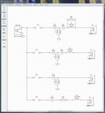
Allen is correct, normal musical decay does reduce demands on high range parts some what... but music is highly variable and not all mixes will follow his averages. So, lets ask the question of what happens if you do send it a full power sine wave sweep from software like REW or a signal generator. Yes, we can accept that most parts have brief tolerances for over-power. But rather than randomly counting on that, lets do a little circuit analysis...
(If nothing else this should be a good learning experience...)
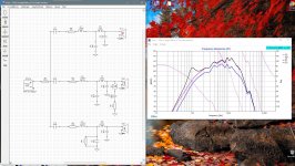
The first thumbnail is the XSim schematic we'll be tampering with. I've also included the DXO so you can play with parts values if you like. I've set the amplifier to 50 watts for this.
To activate each section, switch the lead resistors from open to short.
Be careful to note the left side scales on the rest of the panels as I had to adjust them for some of the examples.
The second thumbnail shows what happens when you enable the top filter, which is yours from your last version. Nice frequency response, btw. But lets look a little deeper into what's happening. Notice that R3 is burning up a lot of watts. Interestingly it's burning more than the tweeter, even though it's in series with it. Also note the currents and how they peak with R1 handling less than the sum of S3 and R3 ... This is indicative of resonance effects.
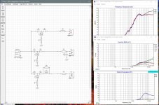
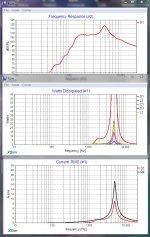
The third thumbnail shows us what's going on. I activated the second version and removed R3, and look what happened... The entire tweeter circuit has stopped being a high pass filter and is now a resonant band pass filter with a very high peak in both current and power dissipation. especially on the tweeter ... enough, in fact, to kill it. The current chart tells us that a lot of power is being drawn that is not reaching the tweeter itself. This scenario could actually happen if R3 in the top version was to fail.
We wouldn't actually use this circuit. But, what we can take from this is that the tweeter circuit is a resonant bandpass filter with R3 doping it down to a very wide bandpass and taking the brunt of the circulating currents to do so. Hence... monster resistor time.
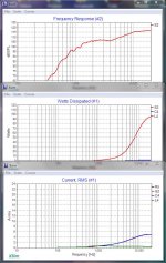
Okay, now on to the fourth one. This time I've enabled the third drawing... a bog standard 2nd order filter. The first thing to notice is that the wattage has tamed itself down very nicely and the currents are pretty sane... but UGH what a horrible frequency response. It's up about 10db at the end.
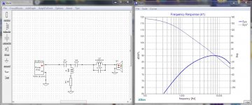
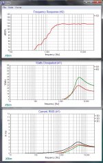
So, how to fix this? The last thumbnail shows an unusual circuit the last one on the schematic, all in series... The frequency response isn't a dead straight line but the biggest errors are in parts of the audio spectrum where A) there isn't much content and B) only the neighbourhood dogs are likely to hear it. It's within plus and minus 3db, so perfectly acceptable. Also note that the wattage load on the components is greatly reduced, R2 is down to 25 watts, the tweeter is getting most of the power and L5 is taking only a small hit as it trims down the response in that last octave for you. So now you can use that 10 watt resistor without worrying about cooking anything.
Here's the thing ... coils behave the same no matter where you put them. If a big one will attenuate higher frequencies from a woofer, a smaller one will do the same from a tweeter. If you aren't hell bent on that perfect straight line, getting "close as makes no difference" can greatly reduce the risk of things going wrong. Plus, if any of the parts in that chain were to fail, your tweeter would simply go silent and probably survive it.
Hope this helps....
Attachments
Last edited:
XSim does not give realistic figures and your resistor is more likely to see much less than 1W at full power based on 6kHz.
Only if you are intent upon burning down the house. XSim gets very close to reality, as measured on test equipment.
Seriously Allen ... how much theoretical knowledge to you have? Have you had any training in AC circuits, at all?
To be clear, -27dB is a five hundred times reduction in power, 30/500= 60milliWatts.does reduce demands on high range parts some what...
With 60 milliWatts I couldn't light a cigarette.Douglas Blake said:Only if you are intent upon burning down the house.
Argumentum ad hominem.Seriously Allen ... how much theoretical knowledge to you have? Have you had any training in AC circuits, at all?
It seems Douglas prefers monologue threads.
It seems, my friend, that this thread comes from me being asked to provide something of an educational experience.
It's pretty simple ...
Got something to say ... say it.
Don't want to learn ... ignore it.
Got a beef with me ... send PMs
- Home
- Loudspeakers
- Multi-Way
- Xsim Critique- taking it to the next level