To be clear, -27dB is a five hundred times reduction in power, 30/500= 60milliWatts.
All true ... until you get a movie like Fast and Furious 5 where they decide to show us what ringing ears after an explosion sounds like and they dump in a 7khz sine wave at -6 dbfs for about 20 seconds.
Look ... I get that what I'm presenting here is not your bog standard lego blocks approach to crossover design. First, that's not how I do things and, second that's not what I was asked about when this started.
Argumentum ad hominem.Seriously Allen ... how much theoretical knowledge to you have? Have you had any training in AC circuits, at all?
So I should take it, then, that your answer is "no".
Last edited:
Lol. But seriously, stop it.So I should take it, then, that your answer is "no".
@Douglas Blake,
Thanks so very very much! That is exactly the educational experience I was looking for when this thread was started. I have learned a great deal already.😀 Once I am able to come up for air this week, I will go through and give a play with the Xsim file you attached. Work on the golf course I manage is starting to take off now that weather is finally starting to warm. Have a great day.😀
Best,
Rich
@Douglas Blake,
Thanks so very very much! That is exactly the educational experience I was looking for when this thread was started. I have learned a great deal already.
My pleasure. I'm always happy for something to keep me busy.
Once I am able to come up for air this week, I will go through and give a play with the Xsim file you attached. Work on the golf course I manage is starting to take off now that weather is finally starting to warm. Have a great day.😀
There probably won't be much of a golf season in Canada, we're all on restrictions because of the virus. If you are working with the public, be sure to take every precaution seriously... and stay safe.
Cheers.
remember it's "projects for fanatics, by fanatics" and there's no standard for verification of the information contained therein...
Thanks @ Douglas Blake,
I will continue to practice social distancing until this crisis passes. It is good that my work is outside and I can avoid interacting with people playing. Take care of yourself as well and be safe.
Best,
Rich
I will continue to practice social distancing until this crisis passes. It is good that my work is outside and I can avoid interacting with people playing. Take care of yourself as well and be safe.
Best,
Rich
remember it's "projects for fanatics, by fanatics" and there's no standard for verification of the information contained therein...
But just think how much better our projects would turn out if we employed REAL engineering and design principles, instead of sillyness like flipping rca cables or replacing opamps and expecting miraculous transformations.
The audio world has always had a core group of fanatics. I have no problem with that, except that in the last 15 years or so, that core group has shifted from the Mark Levensons and Andrew Jones, to a bunch of golden ears who actually think AudioQuest and Monster cables can save a mediocre system. We've gone from "if you change this part, you can reduce the distortion" to "If you push this button, music comes out" ... and it's very sad to watch.
Even the most basic of electronics knowledge would save a lot of the projects I see fail on these pages...
As for verification ... have you looked at my posts? I always demonstrate my ideas either in XSim, LTSpice or by references... nothing I post is unverified or "snakeoil"
Last edited:
hey i didn't create the situation but i have the same misgivings you do...
some of the Nigel Tufnel logic round here makes my head spin...
some of the Nigel Tufnel logic round here makes my head spin...
@Douglas Blake,
That is exactly why I love your posts! You and jReave are great at teaching by concise examples and detailed explanations that even a novice like myself can understand. I appreciate that you both take the time to go into detail regarding the subject matter rather then offering a pithy comment or two and then disappear. Keep up the good work!
Best,
Rich
@Douglas Blake,
That is exactly why I love your posts! You and jReave are great at teaching by concise examples and detailed explanations that even a novice like myself can understand.
I have absolutely enjoyed working with @JReave on a couple of threads lately. In fact, not being a cabinet guy, I've got my own questions for him, when the time comes...

Based on the above statement by jReave, I found a high watt wirewound resistor that might work for this application. I have attached a photo so others with more experience could let me know if it would work better/or at least as well as stacking several 10 watt resistors together.
And you probably thought that was an innocent question! 🙄
Sorry that I may have given you some inaccurate info, or perhaps if not inaccurate then impractical. I'm still not 100% sure which one it is. In point of fact, I am still learning and still making mistakes just like you.
So let's review.
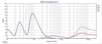
First, conventional wisdom says that HF's will see much, much less power than the LF's. And that is more or less what XSim is telling us when we look at it's power consumption chart. Attached below is XSim's power analysis of your 3-way xo. What we see is that most of the power going into your speaker is going to be below about 200Hz if the musical or in the case of movies, the sound effects content is all of equal SPL level. That later is an important point.
The tweeter circuit is pulling a bit more than the mid which is a bit surprising but not too difficult to understand when you look at the fact that you are using a very high sensitivity mid so it doesn't actually need very much power to achieve high SPL's. What did really surprise me though was the amount of power that R3 is digesting in the tweeter RL filter. At about 40W, that's twice as much as the actual tweeter is using. Without a background in electronics, I can't really give you a reason for this but I'm going to trust XSim and the better minds here than mine on this.
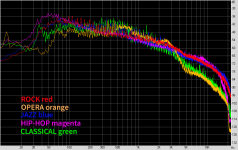
Now the second issue is the one Allen has brought up which is that in most recordings, the SPL levels across the frequency range are not equal. If you look at that same graph from post #74 (re-attached below), we see that after about 100Hz, the SPL of the higher frequencies are falling somewhere between about 3 and 6dB per octave. (I'm still trying to wrap my head around this one because it's here that I would expect to actually see the effects of the Fletcher-Munson curves. So what's happening in the HF's I find confusing.)
So how much wattage do you really need on that resistor in the real world if we go by that FR chart? Let's go back and see what XSim is telling us. Here I've used 60W as the input. Looking at the power chart again, we can see that the peak wattage consumption is at about 6000Hz. Depending on which genre of music you look at, 6000Hz is about 24 - 36dB down from its level at about 100Hz. If that frequency is in reality going to be about 24dB down from what XSim is showing us, then it will only need about .13W (start by using the 40W the resistor sees and then halve the power every time you reduce the SPL by 3dB). So clearly a 10W resistor for R3 is going to be fine under these conditions.
But now the question becomes, what if we operate outside the averages? What if you have very elevated levels in other types of genres, like movies as Douglas has pointed out, and how much is that peak level above the average ever going to be at the frequency we are concerned with. If they are twice as loud that would be another 10dB. Twice as loud as that again would add another 10dB. Is that realistic enough? If we want to accommodate for a possible extra 20dB that means that our wattage usage in that resistor will now go back up to about 20W.
Better to be safe than sorry.
At least, that's what I can put together at this point given my own level of understanding.
Thanks for the kind words as well.
Attachments
Last edited:
And you probably thought that was an innocent question! 🙄
Sorry that I may have given you some inaccurate info, or perhaps if not inaccurate then impractical. I'm still not 100% sure which one it is. In point of fact, I am still learning and still making mistakes just like you.
Not inaccurate... although perhaps a bit beyond common understanding. Certainly what you guys came up with is not an uncommon circuit in a crossover.
Here's the thing ... when an LC circuit approaches resonance it begins storing energy. Below resonance the coil is conducting most heavily, but the capacitor is storing a charge from the coil. Above resonance the opposite happens, the capacitor is conducting and the coil is storing a charge.
At resonance, these stored charges align out of phase and begin to circulate back and forth between the coils and caps as the input polarity reverses, like the square ball on a Pong game. The more attuned they are the bigger this exaggeration becomes. This is called the Q or "quality factor" of the circuit. The higher the Q --the more tightly tuned the parts-- the more exaggerated the response.
For a bandpass filter this causes it to take on a very low impedance. For a bandstop filter we get a very high impedance. ... well beyond that of the parts themselves.
R3 in Montana's and your designs ended up being a "doping" resistor that detuned the resonance effect... but it did it by absorbing all that circulating energy from the coil ... hence the high power dissipation.
If you look at the third thumbnail in my earlier message where I took it out of circuit, you can see just how exaggerated the resonance effects are in that circuit. Most of that resistor's current was *not* coming from the amplifier.
I realise the resonance at that point was a total accident... but there's no denying it's effects or the risk to the tweeter if R3 was to go open. Although the top is cropped to show the lesser currents... the tweeter could have seen upwards of 100 watts as it now took the brunt of the stored energy at resonance. (Yes, designs should also consider Failure Modes)
Even at lower powers and with musical decay... you would still have a lot of circulating current in that part. I certainly would not put a 1 watt part in there... it would probably last just about until the first good symbol crash or police siren.
It is, I think, a good idea that people should read up a bit on resonant circuits and understand just how they can surprise you... There's a good tutorial HERE There are about 5 pages after the first that you need to at least look at to get the whole picture.
Now don't get me wrong ... I'm not blaming or finding fault. I see this kind of thing all the time in lots of different places (not just crossovers) and it does take a somewhat experienced designer to spot it.
Hope this was helpful...
Last edited:
Anticipating your next question...
"Why did that resonate so strongly?"
Take a look at what that RL circuit was trying to do.
First you needed a high pass circuit to bring in the tweeter at about 2500hz. Then you immediately needed that LR circuit to boost the low end of the tweeter's range starting at ... uh huh... 2500hz. This placed the corner frequencies of both filters in very close proximity and they coupled together, effectively becoming one filter, producing a very exaggerated response.
In my fourth circuit from my earlier post, I did not attack the low end of the tweeter, I went after it's high frequency end. The high pass starts at about 2500hz like before but the low pass from the coil does not start until more than an octave higher at about 8000hz. While they would still resonate at some frequency, the coupling was so loose that the resonance would be very weak and could easily be absorbed by the resistor between them.
Thanks for that Douglas. I can almost follow most of it but will probably need a little more time for full comprehension. Or something in close proximity.....😉
But I'm curious if besides the electrical complications, if there is a sonic footprint to these component resonances and ringing you have been talking about. Is this something that you can hear?
But I'm curious if besides the electrical complications, if there is a sonic footprint to these component resonances and ringing you have been talking about. Is this something that you can hear?
It is, and using high power components can have a negative effect at higher frequencies but generally not for speakers.If they are twice as loud that would be another 10dB. Twice as loud as that again would add another 10dB. Is that realistic enough? If we want to accommodate for a possible extra 20dB that means that our wattage usage in that resistor will now go back up to about 20W.
Better to be safe than sorry.
60mW translates to 600mW and 6W, for 10dB and 20dB.
But I'm curious if besides the electrical complications, if there is a sonic footprint to these component resonances and ringing you have been talking about. Is this something that you can hear?
It's like a bell ... no matter how often you hit it, it always rings at the same pitch. How long it rings is a question of it's construction.
I have always suspected it could be audible if the ringing is strong enough, although I've never done the work to prove one way or the other. (I mostly spend my time avoiding it.)
There might be a hint in the way R3 is dissipating more power than S3 in that second thumbnail (Montana's circuit) ... what is actually driving the tweeter? Depending on how long it takes the ringing currents to dissipate there might be some period of time when it is audible.
Last edited:
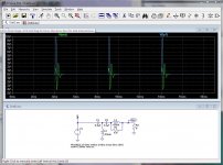
Okay... I sketched the tweeter circuit up in LTSpice and ran a transient analysis on it...
The blue trace is a single pulse applied to the input
The output is the green trace.
Given that it rings for almost a millisecond... I'd have to say "Yes it is going to be audible".
The blue trace is a single pulse applied to the input
The output is the green trace.
Given that it rings for almost a millisecond... I'd have to say "Yes it is going to be audible".
Attachments
Last edited:
- Home
- Loudspeakers
- Multi-Way
- Xsim Critique- taking it to the next level