Actually if that 150Hz dip is just an artifact then I might not worry about it. Splicing in a modeled response will make it look prettier but it won't change an acceptable reality.
Let me know what works best for you: working through it on your own for now or if you'd like me to post the 1st revision I've come up with.
Cheers
Let me know what works best for you: working through it on your own for now or if you'd like me to post the 1st revision I've come up with.
Cheers
@jReave,
I would Love to see your 1st. revision.😀 As you suspected, I did use a modeled low frequency response and it changed very little.
Best,
Rich
I would Love to see your 1st. revision.😀 As you suspected, I did use a modeled low frequency response and it changed very little.
Best,
Rich
Hi guys...
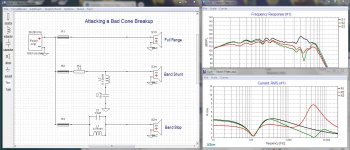
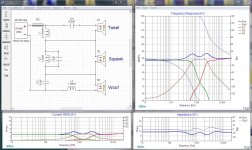
I've been looking at the schematics so far and I can't help noticing that midrange driver as a seriously nasty breakup at about 3500hz.
The best way to attack this is to notch that frequency off of the driver, so that it doesn't break up. But there's more than one way to skin that cat.
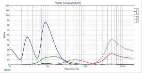
In the thumbnail below I have 3 plots for you.
The first one shows the speaker being driven full range, so we can see the cone breakup. (Black)
The second one shows the usual shunt notch filter and the way it reduces the breakup. (Red)
The third trace shows you an inline notch filter and how it reduces the breakup (Green)
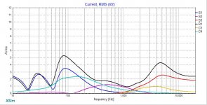
Now comes the surprise... on the current panel you will see that the shunt filter causes a huge whack of current, which is just wasted. But take a look at the inline filter... the current actually goes down and the notch is deeper.
Guess which one I would recommend...
If the filters are too sharp you can add a resistor in series with the shunt filter or you can add one in parallel to the inline filter. Either way will broaden the response a bit.
I've been looking at the schematics so far and I can't help noticing that midrange driver as a seriously nasty breakup at about 3500hz.
The best way to attack this is to notch that frequency off of the driver, so that it doesn't break up. But there's more than one way to skin that cat.
In the thumbnail below I have 3 plots for you.
The first one shows the speaker being driven full range, so we can see the cone breakup. (Black)
The second one shows the usual shunt notch filter and the way it reduces the breakup. (Red)
The third trace shows you an inline notch filter and how it reduces the breakup (Green)
Now comes the surprise... on the current panel you will see that the shunt filter causes a huge whack of current, which is just wasted. But take a look at the inline filter... the current actually goes down and the notch is deeper.
Guess which one I would recommend...
If the filters are too sharp you can add a resistor in series with the shunt filter or you can add one in parallel to the inline filter. Either way will broaden the response a bit.
Attachments

Hi Guys,
Here is my first stab at incorporating some of the ideas that you have put forth. My head is starting to swim.😀 @ Douglas Blake: I will look to add your method to address mid breakup tomorrow.
Best Regards,
Rich
Here is my first stab at incorporating some of the ideas that you have put forth. My head is starting to swim.😀 @ Douglas Blake: I will look to add your method to address mid breakup tomorrow.
Best Regards,
Rich
Attachments

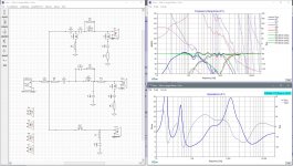
Another excellent explanation from Douglas in post 23. If you look for it in my sim below, you can see what a tanking filter added to the mid inductor does as well. I may change to the parallel notch filter. 😀
I'm a little too tired right now for a full explanation. Everything looks pretty good but there are still a couple of inefficiencies that maybe are livable or that may need improving.
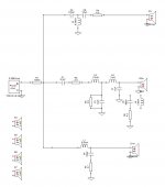
That tweeter was a difficult beast to tame. I tried a shunt capacitor to flatten its rising response but I didn't like what it did with the current. I went instead with a parallel LR filter but looking at the watts chart, R3 is seeing buckets full! I also don't like that there are no resistors on the tweeter meaning that making fine adjustments in level is going to be difficult. I used a series notch filter to tame that waveguide induced rise in the response. I tried a parallel one 1st for the reasons Douglas shows above but I couldn't seem to get it to do what I wanted it to.
I also found an impedance compensation filter on the mid to be essential. Large values there but you can go with an inexpensive cap in that position. An high value iron core inductor is still a bit costly though. But it allowed the mid series capacitor C1 to be massively reduced. That will save you some bucks as that one should be of decent quality. Strangely, the main mid inductor needed to be a fairly large value too.
The woofer was simple. It falls into place very easily with about the same values Paul C used in the Tarkus.
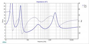
For reference, you might notice that the highest current draws correspond to the lowest points in the impedance response. I used 60W btw to look at the extra charts. Lots of SPL there. But you'll need at least a 150W amp giving you a max of 6amps of current to work with if you want to play it up at those levels.
Play with it as you wish. As I say, there are still some improvements that can be made I think.
Cheers
I'm a little too tired right now for a full explanation. Everything looks pretty good but there are still a couple of inefficiencies that maybe are livable or that may need improving.
That tweeter was a difficult beast to tame. I tried a shunt capacitor to flatten its rising response but I didn't like what it did with the current. I went instead with a parallel LR filter but looking at the watts chart, R3 is seeing buckets full! I also don't like that there are no resistors on the tweeter meaning that making fine adjustments in level is going to be difficult. I used a series notch filter to tame that waveguide induced rise in the response. I tried a parallel one 1st for the reasons Douglas shows above but I couldn't seem to get it to do what I wanted it to.
I also found an impedance compensation filter on the mid to be essential. Large values there but you can go with an inexpensive cap in that position. An high value iron core inductor is still a bit costly though. But it allowed the mid series capacitor C1 to be massively reduced. That will save you some bucks as that one should be of decent quality. Strangely, the main mid inductor needed to be a fairly large value too.
The woofer was simple. It falls into place very easily with about the same values Paul C used in the Tarkus.
For reference, you might notice that the highest current draws correspond to the lowest points in the impedance response. I used 60W btw to look at the extra charts. Lots of SPL there. But you'll need at least a 150W amp giving you a max of 6amps of current to work with if you want to play it up at those levels.
Play with it as you wish. As I say, there are still some improvements that can be made I think.
Cheers
Attachments
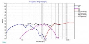
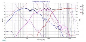
Here's another pic of the FR Graph. The 1 above fails to show what's happening lower down in SPL.
Nice work on the efficiency of your xo Rich. Better than mine I think. But man, I'm not sure I've ever gotten such a ruler flat response before above about 1000Hz. Dang.
I'm going to bed now.
Nice work on the efficiency of your xo Rich. Better than mine I think. But man, I'm not sure I've ever gotten such a ruler flat response before above about 1000Hz. Dang.
I'm going to bed now.
Attachments
@jReave,
Thanks for taking the time to put that excellent schematic together. That is unreal how flat of response you achieved from 1,000 hz up! I will try again tomorrow. This is fun stuff.😀
Have good evening,
Rich
Thanks for taking the time to put that excellent schematic together. That is unreal how flat of response you achieved from 1,000 hz up! I will try again tomorrow. This is fun stuff.😀
Have good evening,
Rich
Thanks so much @Douglas Blake,
I will try to sit down this evening and apply some of the design thoughts/ principles that you have outlined. Let’s see if we can get a very efficient and amp friendly design going.
I hope you don't mind a couple of questions at this point...
Do you have an original set of FRD and ZMA files or are they taken from measurement?
Comparing the graphs to the specs, they really don't match up very well with the published specs. Of course I'm aware the box affects them but not as much as I'm seeing.
Do you have the mid driver in an isolated chamber or is it sharing air with the woofer?
In particular, that 150hz dip in the woofer is puzzling...
Last edited:
@Rallyfinnen,
I will look at adding RC in parallel with L2 and see if I can squash some of the mid breakup.
As for the tweeter w/ waveguide issue, I don't know what to say. I have an adapter installed between the tweeter and waveguide as per Troels Gravesen instructions on his website. Everything appears to be mounted correctly on baffle.
Best,
Rich
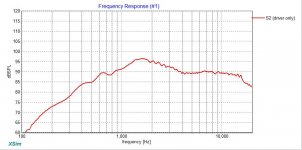
I think you should look in to it, normally you get a big 'bump' in the midrange from a DT300 (and other waveguides) that is usually compensated in the XO, but your raw response looked nothing like it?
The raw response should look at least similar to these examples:
Test Peerless XT25TG-30 / 04 at Waveguide WG-300
Vifa C17WH-
@Douglas Blake
To answer your questions from your post. The files you have are from actual measurements taken with umik1 on axis at 1.5 meters. The mid range is isolated in its own chamber isolated from woofer affects. As for the woofers odd dip, I believe it is my near field measurement method needs to be changed. Maybe use the mic inside the box method. This speaker has dual ports below the woofer in close proximity. I will post some photos today so you can see what I have built.😀
Best Regards,
Rich
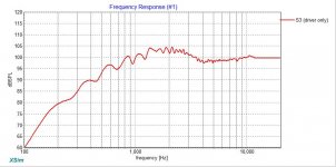
@Rallyfinnen,
I have posted a screenshot of the raw tweeter response from the Xsim file. To me it looks like it there is the rising mid range response that you mentioned. There may be differences do to the fact I measured at a point between tweeter and mid range. I'm not opposed to looking into it more, but I have lost my ability to re-measure until around November. I live and work at a golf course that has a huge dining room with faulted ceilings that makes it nice to measure speakers indoors. But, since we are now open for business I have lost my area to do such things.😡 My plan is to put a crossover together within the next couple of weeks and then double check everything later in the year.
Best Regards,
Rich
Attachments
It's worth noting that cone breakup is an issue that runs deeper than a response peak on one axis, and notching cannot undo its effects.
If you have a speaker breaking up at 3000hz and you don't feed it 3000hz it doesn't break up. It's simple logic.
Which is true in itself, but in many cases, since low pass loudspeaker filters are not generally brick-walls, you are. Whether a cone mode in the nominal transition or stopband amplifies HD lower down depends on how severe it is, how well attenuated it is and the overall motor quality & baseline HD levels. Notching it alone in many cases doesn't help; you can end up with a lovely smooth overall FR and still have annoying colouration, which sometimes gets incorrectly blamed on the tweeter.
Last edited:
@Douglas Blake
To answer your questions from your post. The files you have are from actual measurements taken with umik1 on axis at 1.5 meters. The mid range is isolated in its own chamber isolated from woofer affects. As for the woofers odd dip, I believe it is my near field measurement method needs to be changed. Maybe use the mic inside the box method. This speaker has dual ports below the woofer in close proximity. I will post some photos today so you can see what I have built.😀
Okay, thank you... that explains a lot of what I've been seeing.
Please explain how you did this... Was it outdoors? Was only one driver active? Were the other box openings covered? What was the ambient sound level? etc.
This is a concern because there is a very real chance that if we continue with the current files, you are going to end up with a beautiful set of speakers that will only sound right in one spot in one room ... and if you took your measurements in the middle of your garage, guess where that one spot is going to be.
@ Douglas Blake,
I will try to answer your questions the best I can.
1)Drivers were measured indoors @1.5 meters
2)Measurements taken between tweeter and mid range
3)I tried set up measurement rig away from boundaries by about 8-10 feet.
4)Floor bounce was an issue since I could only elevate speaker to about 4 feet off ground.
5)Only 1 driver at a time was measured. Except to drive tweeter/mid range pair and woofer/tweeter pair to establish offsets in Xsim.
6)Not sure on ambient sound level but noise floor seemed very low. I turned off everything that could/does make noise like furnaces, refrigerators, etc.
7)Inside temperature was around 55-60 if that matters.
Hope that helps,
Rich
But, since we are now open for business I have lost my area to do such things.😡 My plan is to put a crossover together within the next couple of weeks and then double check everything later in the year.
If this is the case, I would strongly suggest that we don't spend a lot of time fine tuning this or adjusting that... just put together a bog standard 3 way crossover based on dummy loads, until you can get better measurements or can find accurate FRD and ZMA files for these drivers.
In my opinion spending the $200 or so on decent parts risks becoming a waste of money, based on your current data.
When I would go out on a "room tune" call, I carried a couple of the crossovers below in my bag. I would hook them up with clip leads just to get some sense of what the speakers sounded like without massively complex circuits ... you'd be surprised how often I ended up installing them permanently.
Attachments
@Douglas Blake
I like your thought process on this. I have some components already and placed an order with Parts Express for the remaining stuff I was missing. This was done before starting this thread. I’m not to worried about having a few spare parts on hand. There is another build in the hopper after this build. It will be a large floor stander 3 way. At least the wife does not have to pull me out of bars.😀
Best,
Rich
@ Douglas Blake,
I will try to answer your questions the best I can.
...
Hope that helps,
Rich
That explains what I'm seeing, then. Even at 1.5 meters, we are seeing room effect, although it's probably minor... but unless we know what it is, we can't ignore it. Tuning from that risks the phenomenon of a speaker that only sounds right in one small spot.
Again... no offence and nothing personal ... but I don't think you should press on until you can get better measurements.
My work seldom involved designing baffles, so I'm probably not the right person to advise on this point, but let me suggest that "close mic" when measuring drivers actually means "an inch or two".
- Home
- Loudspeakers
- Multi-Way
- Xsim Critique- taking it to the next level