The key is to flatten out of band amplitude as best you can thru the intended summation region, knowing that it will be 'undone' when the crossover is added.....has a logical elegance to it imho. (learned it from Pos/rePhase)
Some tools are desined for this kind of procedure but it's waste of resources or even bad decision due to possible clipping with analog system and digital biquad applications knowing that each band can be optimized directly to target without equalizing flat before crossing. This is certainly not an issue with limitless FIR and typical tools for it, but it does not make it elegant, imho. Maybe logical, but not efficient/rational.
Anyway, some randomly or subjectively selected transfer function target response and how accurately (e.g. within 0.5 dB down to -60 dB below nominal sensitivity) acoustic responses imitate the target does not define sound quality. Especially if we're talking about axial responses only, forgetting/ignoring off-axis, power etc.
Therefore discussion about theoretical limits to produce e.g. EXACTLY LR6 acoustical response is really invaluable. We can and sometimes should make compromises other than some ideal textbook responses to design better speaker.
Vacuphile: That is why all embedded systems I know of work with the workflow I described.
Could it be that workflow is not so much über rational, but dictated by the limitations of the software used? To my best of knowledge Sigma Studio, MiniDSP, Hypex software simply does not allow direct design of FIR filters, but rather rely on “after” convolution through e.g. Rephase in order to properly program DSP chips such as e.g. ADAU 1701 or 1452, whereas Ultimate Equalizer (and maybe Accourate?) can achieve FIR design directly?
Could it be that workflow is not so much über rational, but dictated by the limitations of the software used? To my best of knowledge Sigma Studio, MiniDSP, Hypex software simply does not allow direct design of FIR filters, but rather rely on “after” convolution through e.g. Rephase in order to properly program DSP chips such as e.g. ADAU 1701 or 1452, whereas Ultimate Equalizer (and maybe Accourate?) can achieve FIR design directly?
Some tools are desined for this kind of procedure but it's waste of resources or even bad decision due to possible clipping with analog system and digital biquad applications knowing that each band can be optimized directly to target without equalizing flat before crossing. This is certainly not an issue with limitless FIR and typical tools for it, but it does not make it elegant, imho. Maybe logical, but not efficient/rational.
Anyway, some randomly or subjectively selected transfer function target response and how accurately (e.g. within 0.5 dB down to -60 dB below nominal sensitivity) acoustic responses imitate the target does not define sound quality. Especially if we're talking about axial responses only, forgetting/ignoring off-axis, power etc.
Therefore discussion about theoretical limits to produce e.g. EXACTLY LR6 acoustical response is really invaluable. We can and sometimes should make compromises other than some ideal textbook responses to design better speaker.
Who said anything about theoretical discussion to produce EXACTLY LR6 ?
At some ridiculous 'within 0.5dB down to -60 dB' ?
Who even said anything about ideal textbook responses?
Just you, looking for something to push against I guess....
Look, everything I've learned about the tuning method I advocate has been via dual channel measurement.
I've literally made thousands of them over the last 4 years with speaker building as a full time hobby.
Built nearly 30 speakers now, including/ranging from 3 kinds of subs, 4 hornloaded MTMs, 6 versions of arrayable modular traps, a coax surrounded by a large waveguide, CBT line arrays, corner line arrays, and lately 3 versions of synergies.
Every one started with a little basic simulation to get construction started, then constantly making measurements step by step through construction and tuning.
All eventually met their design objectives after culling prototype mistakes.
All ended up being tuned via the same output FIR method I've been suggesting....… both on and off axis....with most measurements made outdoors using a 3 mic pivoting boom, and a turntable, for off axis tuning.
IIR crossovers were often compared, as half of the boxes were built for hi-fi PA and sometimes needed to be able to be used for low latency live sound.
And frankly, having constructed maybe 1000 FIR files for all the speaker builds and tested them both on and off axis, if I see a textbook perfect response from a real speaker, I know somebody slapped an overcooked FIR fix on a singe spot to post some pretty measurements. Embarrassingly, I was guilty of that too in my early days...overjoyed at the ease and of the results.
I'm the last guy that will tell someone to shoot for perfect textbook acoustic response, but I'm one of the first guys to say it's easier to get final acoustic response closer to textbook than some folks seem to think, as I observe them slug through legacy tuning methods.
The method works...it's the most pragmatic, logical way to tune I've found so far.
But I'm always open to a better mousetrap...if you have one, please hit me with it.
Cause all I've heard so far is stonewalling, that makes no sense up against my experiences...
I always thought (because minidsp 2x4HD only allows output FIR) that use of FIR was simply a better way to equalize independently powered drivers prior to applying a crossover between them, because FIR can align both amplitude and phase prior to enabling a crossover. To get that cross to add perfectly, I presumed phase must match prior to applying the crossover?
Is there a hidden advantage to IIR that I am missing?
Hi Peter,
imso, you're not missing anything with IIR, unless you need to minimize latency.
I don't agree with that. If you know how to do it you can of course use the same principles to reach acoustic target functions with IIR as you would with analog methods (except at higher frequencies due to the warping of the frequency axis). But if you use a GUI that is restricted to just cascading filter blocks then it is of course not possible.
Regards
Charles
You can not do it with analog either. The best you can do is get close if the driver rolls off pretty smoothly in the first place. But if the driver has break up modes in the stop band you are going to pile stage after stage of bi-quads to follow the target to the point that it's impractical. With FIR it's one and done.
Last edited:
Boden, I think it is more that hardware price goes up with speed and capability, so clever designers take the convolution afterwards approach. Unfortunately, MiniDSP is software limited to the other approach, otherwise it would be more capable.
However, no skin of my nose, since I really don't think linearizing phase is worth the bother because significantly inaudible. It may be good for marketing purposes, though.
However, no skin of my nose, since I really don't think linearizing phase is worth the bother because significantly inaudible. It may be good for marketing purposes, though.
Who even said anything about ideal textbook responses?
Just you, looking for something to push against I guess....
phase_accurate and john k... are discussing acoustical textbook LR4.
Method you're suggesting (make flat and then cross) creates also acoustical textbook responses by default without compromising adjustments.
That is also totally okay for me if off-axis and power etc. are okay and drivers support wide frequency range, but e.g. john k...'s "With FIR it's one and done" is at least possible to understand so (maybe wrong) that some fancy algorithm in filter design program creates FIR coefficients which produce flat response before XO, without evaluating e.g. drivers' actual capabilities to produce flat response outside XO frequencies. Not much sense to force response to ideal textbook if it requires e.g. boosting of +30 dB below and/or above frequency range driver is able to pressurize (with decent distortion), and DAC and power amplifiers within output range without clipping. So there's not that much difference to IIR with cascaded biquads in real life imo, if using of brain is preferred over academic nitpicking.
But I'm always open to a better mousetrap...if you have one, please hit me with it.
We use different platforms for crossovers. You have PC hardware, convolver app and multi-channel sound card. I could not use that complex (smelling diy) system for commercial designs, and not too much interested for personal use due to other family. Measurement and design methods and tools support anything, and I really don't have mental stonewalls preferring legacy systems only. Just some practical limits related to availability of dsp+amplifier products.
phase_accurate and john k... are discussing acoustical textbook LR4.
Method you're suggesting (make flat and then cross) creates also acoustical textbook responses by default without compromising adjustments.
That is also totally okay for me if off-axis and power etc. are okay and drivers support wide frequency range, but e.g. john k...'s "With FIR it's one and done" is at least possible to understand so (maybe wrong) that some fancy algorithm in filter design program creates FIR coefficients which produce flat response before XO, without evaluating e.g. drivers' actual capabilities to produce flat response outside XO frequencies. Not much sense to force response to ideal textbook if it requires e.g. boosting of +30 dB below and/or above frequency range driver is able to pressurize (with decent distortion), and DAC and power amplifiers within output range without clipping. So there's not that much difference to IIR with cascaded biquads in real life imo, if using of brain is preferred over academic nitpicking.
You don't boost anything. You don't flatten first and apply a filter. You design the filter to do what you want. I'm borrowing a figure from the Bodzio web site.

You chose the frequency range over which you want to match the acoustic target and calculate the required filter transfer function, then implement it using FIR. If you had the UE software you would see that you can limit the range of the match, and you can preprocess the measured driver response if you don't want to EQ every little bump and dip. But it is not EQ flat and apply a text book filter. It O = F x D, where O is the filtered acoustic output, F is the filter and D is the measured driver response. Then, F = O / D.
Now, look at the figure of the raw driver response. Look at the area between 300 and 500 Hz. Tell me, how many stages of IIR filtering would be required to match the LR4 roll off between those frequencies.
This is not academic nitpicking. It's real world engineering and software that has been around for 10 years now. You simply aren't familiar with it and are speaking from a position of ignorance.
Last edited:

I'm guessing that's why this thread has "exercise" in the title 😉However, no skin of my nose, since I really don't think linearizing phase is worth the bother because significantly inaudible.
I'm finding it interesting from method to end result aspect
phase_accurate and john k... are discussing acoustical textbook LR4.
Method you're suggesting (make flat and then cross) creates also acoustical textbook responses by default without compromising adjustments.
That is also totally okay for me if off-axis and power etc. are okay and drivers support wide frequency range, but e.g. john k...'s "With FIR it's one and done" is at least possible to understand so (maybe wrong) that some fancy algorithm in filter design program creates FIR coefficients which produce flat response before XO, without evaluating e.g. drivers' actual capabilities to produce flat response outside XO frequencies. Not much sense to force response to ideal textbook if it requires e.g. boosting of +30 dB below and/or above frequency range driver is able to pressurize (with decent distortion), and DAC and power amplifiers within output range without clipping. So there's not that much difference to IIR with cascaded biquads in real life imo, if using of brain is preferred over academic nitpicking.
We use different platforms for crossovers. You have PC hardware, convolver app and multi-channel sound card. I could not use that complex (smelling diy) system for commercial designs, and not too much interested for personal use due to other family. Measurement and design methods and tools support anything, and I really don't have mental stonewalls preferring legacy systems only. Just some practical limits related to availability of dsp+amplifier products.
Gotcha. Thanks for all the clarifications.
Yes...with regards to potential problems with applying too much out of band boost for the method I suggest...
What I do is look at the final processing curve that is the sum of the EQ boost and the crossover. If it doesn't roll off with sufficient order to protect the driver, I know to increase the order or the crossover.
However, this is never an issue because I typically use 16th order LRs due to the better polars I measure with steeper.
Sorry if I gave the impression I use a PC and multi-channel soundcard. I mentioned those right before saying I use Q-SYS. Sounds like you need to stay away from DIY-like solutions for commercial reasons.
If you haven't encountered it, Q-SYS is probably the most advanced A/V commercial install platform available.
Q-SYS Designer Software - Software and Firmware - Resources - QSC
The Core processors are Linux boxes that use the q-sys Designer software to compile from Win PC's whatever design you need, and then run without further need of PC. The model I have is Core110f.
Core 110f - Q-SYS Cores - Products, Peripherals & Accessories - Q-SYS Ecosystem - Products - Systems - QSC
You can even embed dual channel analyzers into the design while you build/trouble shoot...although the Core110f only allows one instance.
I almost grabbed a used Core3100 on ebay for a little over $2k, that is the same unit that runs all the in house audio for the second largest convention center in the US. Just couldn't justify it when already having the 110f.
I really can't say enough about q-sys...🙂
This is not academic nitpicking. It's real world engineering and software that has been around for 10 years now. You simply aren't familiar with it and are speaking from a position of ignorance.
I've had SE until ver 12 and have EquAPO and rePhase and VCAD and everything else needed to implement FIR filters so you can stop b.s. talk about ignorance. I was talking about exceeding range of driver. Sorry if my English is still as bad as it has been last 55 years.
Show for example how brilliant LP slope is with that driver and FIR to 30-60 deg off-axis, and evaluate where you would set LP freq to maintain logical behavior. And then listen audibility of resonances also to off-axis and tune if required and finally count required biquads. Single axial with nice square wave might not be that valuable...
Last edited:
I use Rephase, and aside from the necessity of exporting/importing filters, it’s no more burden to use FIR instead of IIR. The interface is no more complex, (IMO) than the IIR filter interface inside minidsp’s control panel.
I perceived that it should be a significant benefit to use FIR prior to applying L-R cross, because I understand proper LR summation requires that you do have matching delay/phase at the intended cross frequency. Don’t know that it’s possible to assure that with IIR? I also don’t know how much any of this pragmatically matters...many folks claim not at all.
Reading this forum has increased my doubts about all of this.
I could load two channels with identical compensation curves, one with IIR, other with FIR gain/phase corrections. If audible differences I should detect it, and could also compare how well the two drivers add together compared to measured results.
You don't boost anything. You don't flatten first and apply a filter. You design the filter to do what you want. I'm borrowing a figure from the Bodzio web site.
You chose the frequency range over which you want to match the acoustic target and calculate the required filter transfer function, then implement it using FIR. If you had the UE software you would see that you can limit the range of the match, and you can preprocess the measured driver response if you don't want to EQ every little bump and dip. But it is not EQ flat and apply a text book filter. It O = F x D, where O is the filtered acoustic output, F is the filter and D is the measured driver response. Then, F = O / D.
Now, look at the figure of the raw driver response. Look at the area between 300 and 500 Hz. Tell me, how many stages of IIR filtering would be required to match the LR4 roll off between those frequencies.
This is not academic nitpicking. It's real world engineering and software that has been around for 10 years now. You simply aren't familiar with it and are speaking from a position of ignorance.
I haven't use the bodzio software, but I use a FIR generator, FirDesigner that works in similar fashion. You make an acoustic target curve, and let the software generate the FIR file that moves measured response to match the target over the freq range you choose. FIR Filter Design Software for Loudspeakers. FIR + IIR. | ECLIPSE AUDIO
I used rephrase for a year of so before getting FirD, where everything is done manually.
What I came to realize is that manual flattening out of band, and then adding a crossover give the same net filter as the automated FirD process.
Maybe not as exactly precise, but so close they are the same.
So I recommend the out of band flattening approach simply because it doesn't require an automated piece of software to do target matching.
And I do think it's a piece of simple logic that helps demystify crossover design.
The difference comes down to you wanting to insert text book filters as this only works under those conditions.because I understand proper LR summation requires that you do have matching delay/phase at the intended cross frequency. Don’t know that it’s possible to assure that with IIR? I also don’t know how much any of this pragmatically matters...many folks claim not at all.
I've had SE until ver 12 and have EquAPO and rePhase and VCAD and everything else needed to implement FIR filters so you can stop b.s. talk about ignorance. I was talking about exceeding range of driver. Sorry if my English is still as bad as it has been last 55 years.
Show for example how brilliant LP slope is with that driver and FIR to 30-60 deg off-axis, and evaluate where you would set LP freq to maintain logical behavior. And then listen audibility of resonances also to off-axis and tune if required and finally count required biquads. Single axial with nice square wave might not be that valuable...
Frankly, you same question about off axis apply equally to any filter or crossover design. How the speaker behaves off axis is more a function of choice of driver and crossover point, not how well the filter is designed, or what approach is used; FIR, IIR, active or passive analog,...
The example is not so much about how "perfect" the response is at - 30db, but rather how the behavior between 100 and 500 Hz is dealt with, the critical crossover region. And I don't particularly care about the linear phase aspect.
And again, this is not EQ flat and filter. There is no exceeding the drivers range.
Last edited:
How the speaker behaves off axis is more a function of choice of driver and crossover point, not how well the filter is designed, or what approach is used; FIR, IIR, active or passive analog,...
Exactly. I understand that your point/message was much simpler than my "what is good design method". In practice we should investigate also listening window, off-axis, power and non-linearities and after that evaluate how many filters are really needed and what XO points could be. That approach will not exaggerate significance of single curve giving possibly wrong and harmful information that maximum accuracy of TF is valuable and numerous biquads or FIR is mandatory.
My point/message could be for example that "predicted excessive complexity of filter does not necessarily tell that designer needs FIR or numerous biquads. Maybe just bad priorities and design method".
Anyway, this is very much OT so I quit now believing that I've repeated this same sht already too many times. 🙂
Hi,
I posted earlier on VituixCAD thread, however this one seems more suitable. I wanted to achieve the goals that you were talking about in this thread and stumbled upon, a problem with low impedance. I was wondering whether this plays a great role when you use Hypex D-class amp which is capable of delivering in 2 ohms.
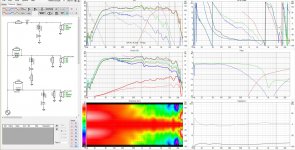
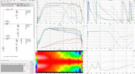
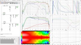
With the help of VituixCAD, very nice piece of software, I managed to get: rather flat frequency response, flat directivity index, good impulse response, flat impedance and phase but it payed for it with an impedance of 2,1ohm almost all across frequency spectrum - “2,5 way crossover v1.jpg”. Then I modeled two more variants “2,5 way crossover v2.jpg” with minimum impedance of 5ohm at 260Hz and “2,5 way crossover v3.jpg” with min imp of 3,2 at 250Hz. Somehow, I couldn’t get time coincidence as good as in “2,5 way crossover v1.jpg”. Maybe I need to work with it a little more. I was wondering what compromise is wise in this case between those three variants. I am going to test it in real life but before I do, I really would like to hear what are your thoughts. I would really appreciate your input.
Bartosz
I posted earlier on VituixCAD thread, however this one seems more suitable. I wanted to achieve the goals that you were talking about in this thread and stumbled upon, a problem with low impedance. I was wondering whether this plays a great role when you use Hypex D-class amp which is capable of delivering in 2 ohms.
With the help of VituixCAD, very nice piece of software, I managed to get: rather flat frequency response, flat directivity index, good impulse response, flat impedance and phase but it payed for it with an impedance of 2,1ohm almost all across frequency spectrum - “2,5 way crossover v1.jpg”. Then I modeled two more variants “2,5 way crossover v2.jpg” with minimum impedance of 5ohm at 260Hz and “2,5 way crossover v3.jpg” with min imp of 3,2 at 250Hz. Somehow, I couldn’t get time coincidence as good as in “2,5 way crossover v1.jpg”. Maybe I need to work with it a little more. I was wondering what compromise is wise in this case between those three variants. I am going to test it in real life but before I do, I really would like to hear what are your thoughts. I would really appreciate your input.
Bartosz
Attachments
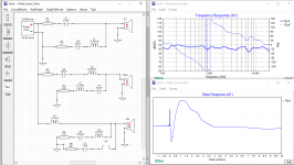
Having read some of the posts here, it seems like some do not think having "0 phase" does not mean "better".
Let's take an example of a typical 3way with inverted polarity as attached below. As you can see, the high frequency is 360 degree leading the low frequencies as seen from either the freq. plot or the step response plot.
For example, when a drum is struck, the high frequency contents of the drums will arrive at your ears 360 degree before the low frequencies. This is an objective fact and cannot be argued. If you have a speaker with inverted polarity, the high freq. will either lag or lead the low frequencies. In this case, the high freq. leads by 360 degrees.
At this point, there are two ways to look at this:
1. The ears are not very sensitive to the 360 phase shift therefore it does not matter. You can't hear it anyway therefore 0 phase shift does not matter.
2. If there ears can detect this, then it should make a difference and therefore having 0 phase shift is a good thing. There are studies that seem to suggest the ears can detect this.
Attachments
Last edited:
We know crossovers not minimum phase either, unless they are linear phase FIR crossovers. Again, any correction post crossover is valid to a single point in space only.

crossover points 135,400 and 5770. cant move the drivers so delay is used
Last edited:
- Home
- Loudspeakers
- Multi-Way
- An exercise in converting a speaker to time-phase coherent