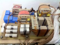
My question was whether a Passive XO can do everything a DSP can? I didn't think that a passive could do what a DSP can. I attach a photo of the passive XO that was designed for me. You may not be able to appreciate how large it is. At the moment (with one stereo amp) it still sounds better than my DSP with 6 amps. I do not have the circuit diagram and the person who designed it for me is now ill, so I don't want to bother him.
I still hope that my DSP solution will sound better when configured correctly.
I still hope that my DSP solution will sound better when configured correctly.
Attachments
The short answer is no. A passive xo cannot do everything what a DSP can, and the passive network can easily become too complicated if we try to copy the response of a DSP xo.
The biggest drawbacks of the passive xo is that the endresult depends on the driver's impedance and the xo network sits between the amp and the drivers.
The high impedance created by the xo network flushes the driver's Qes to the toilet and that's audible i think.
The biggest drawbacks of the passive xo is that the endresult depends on the driver's impedance and the xo network sits between the amp and the drivers.
The high impedance created by the xo network flushes the driver's Qes to the toilet and that's audible i think.
Last edited:
Hi Steve,
Re. your post #99. The method I personally use to design active Xovers employs software having optimisers to accurately generate filters to match target responses and is definitely not suitable for DIY use.
So for this reason I would encourage you to carry on with the method that DeniBeni is showing you, especially since he is the one (as you pointed out) that first suggested you use a target response.
The target response in ARTA only generates a target response curve. It is simply a visual aid that provides a means to check if your acoustic response (via your Xover) matches the response of the target curve.
In order to generate a target curve for an LR4 LPF at 500Hz with its passband set to a level of 135dB, all you have to do is enter the values I show in the attachment of my last post.
One thing I forgot to mention in my last post is that with near-field measurements there is an upper frequency limit to its accuracy that depends on the drivers diameter. For the Focal Audiom 15 WX it will be at approximately 332Hz. You can check this out via this link: HiFi Loudspeaker Design . Hope this helps.
Peter
Yes, target response overlay comes in handy as PLB suggested, especially with the tweeter, where in your case you don't want to measure without crossover filter.
Just measure the tweeter only (with xo filter) and compare the response to the 2kHz LR4 target overlay or whatever xo you want to use and correct the response according to that overlay. It's slightly harder to do this way than flattening first, because the response has to be aligned to a curve and thus harder to visualize, but can be done with a little practice.
Just measure the tweeter only (with xo filter) and compare the response to the 2kHz LR4 target overlay or whatever xo you want to use and correct the response according to that overlay. It's slightly harder to do this way than flattening first, because the response has to be aligned to a curve and thus harder to visualize, but can be done with a little practice.
The "target response curve" approach will work will if:
There are some crude approaches to improve the phase alignment, like reversing the leads on one or more drivers or adding another filter to increase the phase rotation, but these are mostly shots in the dark unless there is accurate modeling of the output from the drivers in the loudspeaker system that carefully accounts for all the phase relationships.
- Your acoustic centers are well aligned and so is the phase between highpass and lowpass filters, or
- You happen to get lucky with phase alignment
There are some crude approaches to improve the phase alignment, like reversing the leads on one or more drivers or adding another filter to increase the phase rotation, but these are mostly shots in the dark unless there is accurate modeling of the output from the drivers in the loudspeaker system that carefully accounts for all the phase relationships.
Of course, the phase response of more drivers cannot be aligned to all point in space.
So all we can do is to align the phase in the gated measurement around the main listening axis.
If all the drivers follow their LR4 response you only need to adjust the delay of one driver to the next in row around the choosed axis and you get a good phase match for that two driver.
So all we can do is to align the phase in the gated measurement around the main listening axis.
If all the drivers follow their LR4 response you only need to adjust the delay of one driver to the next in row around the choosed axis and you get a good phase match for that two driver.
I'd like to see you prove this, and certain other assertions..denibeni said:The high impedance created by the xo network flushes the driver's Qes to the toilet and that's audible i think.
It's a shame to see such passionate conjecture.
Which may explain why some can do it while some ask for assistance.More conjecture, please show me the numbers.
Since when is this a thing?
Ohh AllenB, a loyal follower of the passive crossover cult. Are you serious?
For good reason I wrote that the short answer is "cannot". Yes the long answer would be that you can do all the things passively, but i don't think it's worth the effort.
For example, please make us an LR4 curve from an LR2 in a few clicks and then set the timings of the drives with microsecond accuracy to each other in a minute and in a way that it only takes time. Sure, you can approach it passively, but it won't work the same way, i'm sorry.
By the way, i've built quite a few passive crossovers, and i liked it, so i'm aware of it.
But anyway, I don't think this is the place where we have to deal with such disputes yet. So please give us some constructive tips for this active DSP project, we are curious.
Last edited:
I'd like to see you prove this, and certain other assertions..
If you think that a high impedance network (like a passive crossover) between the amp and the drivers is not spoil the driver's Qes, then i don't know what to say.
Great, thanks the info!I've been doing active crossovers since last century
Define this. Use numbers please, you can't handwave when you use numbers.high impedance network
Define this. Use numbers please, you can't handwave when you use numbers.
Sorry, the high impedance designation can be misleading as a very small (e.g. 0.1 Ohm) serial resistance (like an inductor's series resistance) may be sufficient to cause a measurable degradation of a driver's Qes.
And again, sorry for writing bad about passive crossovers, i don't want this thread to be a passive vs active debate.
Electrical_Factors
Last edited:
Neither do I. It just seems that the crossovers that were made for Steve are probably a good thing. I'm sure this won't sway Steve from experimenting for himself
0.1 ohms may seem comparable to the output impedance of an amplifier. In fact the most significant resistance in the damping current path is neither of those. It is the voice coil resistance, by an order of magnitude.
0.1 ohms may seem comparable to the output impedance of an amplifier. In fact the most significant resistance in the damping current path is neither of those. It is the voice coil resistance, by an order of magnitude.
It does not matter what is the most significant resistance, the additional resistance is always evil because if it is in the circuit, it worsens the Qes. On the other side, the voice coil cannot be subtracted from the equation because without voice coil the driver cannot move and the Qes is measured with the voice coil in the circuit anyway.Neither do I. It just seems that the crossovers that were made for Steve are probably a good thing. I'm sure this won't sway Steve from experimenting for himself
0.1 ohms may seem comparable to the output impedance of an amplifier. In fact the most significant resistance in the damping current path is neither of those. It is the voice coil resistance, by an order of magnitude.
Is Q=0.1 better than Q=0.2? It doesn't work like that, does it?
Yes, 0.1 is better than 0.2 if we think of it in an abstract way, but in reality of course it depends. But with a more realistic example, a Q=0.7 is better than Q=1.2 for a sealed woofer alignment if your goal is objectively better sound quality, of course this then depends on the room acoustics and the listeners ears but in an anechoic chamber the 0.7 wins objectively so it's better for a faithful sound reproduction.
So the additional resistance is only increase the Qes not worsens it, sorry! Are you happy enough?
For another example: just check what happens to a normal midrange driver if you apply a passive first order electrical filter ( a series capacitor) to it. The increasing impedance towards lower frequencies of that highpass filter is increase the driver's Qes, and around the Fc the driver starts to ring in the time domain, which is bad enough. Of course you can compensate with another passive circuit but with an active crossover, you don't have to solve such a problem because it doesn't even come up, much more elegant, does it?
Hi guys,
The reason for my question about Passive and DSP is that the person who designed my Passive for my 3 way speakers did a very good job. So far, the passive with one stereo amp still sounds better than my DSP with the six amps. But this is surely me not mastering the DSP yet?
I haven't yet managed to flatten the freq response, but getting there. Only trouble is that I now find phase and Target Resposes to deal with. I was not till recently aware that Filters and Crossovers modify the phase.
Not sure whether I previously explained how I chose the Xover freqs. I looked at manufacturer's freq responses and where the still flat response overlapped with the still flat part of its neighbour's response, I chose the mid pt (approx) That would be my Xover freq. I think that I have been criticized for this and perhaps they're right because my measurements of the drivers is hardly any where flat. Then this is where I get shot. I wanted as steep a XO slope as possible to avoid neighbouring drivers reproducing the same freqs
- Status
- This old topic is closed. If you want to reopen this topic, contact a moderator using the "Report Post" button.
- Home
- Loudspeakers
- Multi-Way
- Freq measurements and Hypex Filter Design adjustments