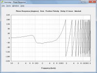
Was not expecting the thousand+ degrees of phase rotation in the pass band
The phase response chart in Hornresp shows the phase-angle difference in degrees between the input signal voltage and the output sound pressure of the loudspeaker system. In the case of a horn loudspeaker, the longer the horn the greater will be the overall phase shift. At 1000 Hz a horn with a length of 103.2 cm is 3 wavelengths or 1080 (3 * 360) degrees long, assuming that the speed of sound is 344 metres per second. The actual phase difference through the horn as calculated by Hornresp will be slightly different to that given by the above simplistic calculation, but the general principle remains the same.
The phase shifts through the driver and throat chamber (if present) are also taken into account.
also appears that horn rolls off closer to 24dB per octave than 12.
The slope tends towards 12 dB / octave as the frequency decreases. For the simple single-segment exponential horn example I gave, the SPL at 20 Hz is 67.3055 dB and the SPL at 10 Hz is 55.0740 dB. The difference between the two levels (one octave apart) is 12.2315 dB.
If I recall correctly, applying a delay equal to the path length of the horn (or path length + one meter?) flattens the simulation's phase response over the flat amplitude region of the horn.
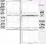
Standard wrapped phase is displayed by default. The Delay tool can be used to add a linear phase offset as shown in the attachment. The default offset delay correction value is equivalent to the mean group delay across the -12 dB delimited SPL bandwidth.
Attachments
so 90 degree phase lag at 10Hz would be equivalent to 25ms of group delay (GD)
It's equivalent to a time delay of 25 milliseconds, which is not the same as group delay.
The group delay will depend on the instantaneous rate of change of phase at 10 Hz, not just on its absolute 90 degree value.
Have you read Post #8456?
The first attachment shows a phase response wrapped between +/- 180 degrees. The second attachment shows the same phase response unwrapped.
Thanks. It's nice to see charts individually sometimes.
No, you said "quantisation"...
Right, but you said there was no quantization.... different word wirh a different definition
You also said that Jesus is the reason for the transient distortion… He cannot be paid the loan because I see distortion in the amplitude… how can phase manipulate amplitude in the start up transient when there's only one signal?
Last edited:
how can phase manipulate amplitude in the start up transient when there's only one signal?
Transient signals cover a broad range of frequencies. The phase response doesn't manipulate the amplitudes of the spectral components but by how much each component is phase-shifted. That's why the shape of a transient signal changes when there is non linear phase response (i.e. group delay distortion).
Regards
Charles
Last edited:
Transient signals cover a broad range of frequencies. The phase response doesn't manipulate the amplitudes of the spectral components but by how much each component is phase-shifted. That's why the shape of a transient signal changes when there is non linear phase response (i.e. group delay distortion).
Regards
Charles
Excellent description. Thank you.
Camplo,
Wasn't the waveform you plotted for a horn at 'cutoff freq'?
Because if yes then in Fluid post number 8437 where do you locate cutoff? Isn't it an effect on amplitude?
And could you point me to where you found the Lavry quote ( post 8394) as i would like to see the context in which it had been said please?
Last edited:
David,The phase response chart in Hornresp shows the phase-angle difference in degrees between the input signal voltage and the output sound pressure of the loudspeaker system. In the case of a horn loudspeaker, the longer the horn the greater will be the overall phase shift.
The slope tends towards 12 dB / octave as the frequency decreases. For the simple single-segment exponential horn example I gave, the SPL at 20 Hz is 67.3055 dB and the SPL at 10 Hz is 55.0740 dB. The difference between the two levels (one octave apart) is 12.2315 dB.
Standard wrapped phase is displayed by default. The Delay tool can be used to add a linear phase offset as shown in the attachment. The default offset delay correction value is equivalent to the mean group delay across the -12 dB delimited SPL bandwidth.
Had forgot the Hornresp default does not include time of flight compensation as is normally used when measuring, or aligning a horn with a longer acoustical path length to a "front loaded" driver.
It appears including a time of flight offset delay correction would reduce GD and "phase wraps" in the horn to similar values as IIR filters with the same frequency response.
Thanks again,
Art
Attachments
Camplo,
Wasn't the waveform you plotted for a horn at 'cutoff freq'?
Because if yes then in Fluid post number 8437 where do you locate cutoff? Isn't it an effect on amplitude?
And could you point me to where you found the Lavry quote ( post 8394) as i would like to see the context in which it had been said please?
There are waveforms for an axi+horn....and...a 4" woofer with a port tuning of 70hz
Amplitude distortion is shown in either....characteristics seem to be predictable based on group delay
I chose places where group delay was peaking and compared them to the area of opposite gd performance for the horn...both spots are below cutoff....for the woofer, I used a filter for the second "high" Gd snap shot
The labery quote is here Amplitude domain - LavryEngineering
Last edited:
Labeyri? Are we talking 'foie gras'? 
Foie gras de canard entier du sud'-'ouest Degustation '-' Labeyrie
I agree Lavry to be tasty too though.
Ok joke off, thank you.
As pointed by Wesayso i don't get your point about the waveform then: you won't ever use an horn there and there is chance this will be masked by the way below them in use.
Last edited:
there is chance this will be masked by the way below them in use.
Not so much masked as "corrected".
Hi Earl,
By how much it is below cutoff? We don't know.
For the horn i've used ( eg: th-4001) the lower limit usually accepted for a good result is around 480hz ( for what i've seen) if this is then at 120hz we observe this behavior Camplo posted, given the kind of high pass filter i've seen used level will be down by something like 24db iirc for horn+cd.
The 15" used to reproduce the lower freq will be dominant and will mask the issue. Edit: yes corrected if that is more apropriate.
Does it seems clearer?
Sorry i'm frustrated to not be more accurate but as i pointed before i'm not even this clear in my own language with this so i understand it can be confuse in English.
...both spots are below cutoff...
By how much it is below cutoff? We don't know.
For the horn i've used ( eg: th-4001) the lower limit usually accepted for a good result is around 480hz ( for what i've seen) if this is then at 120hz we observe this behavior Camplo posted, given the kind of high pass filter i've seen used level will be down by something like 24db iirc for horn+cd.
The 15" used to reproduce the lower freq will be dominant and will mask the issue. Edit: yes corrected if that is more apropriate.
Does it seems clearer?
Sorry i'm frustrated to not be more accurate but as i pointed before i'm not even this clear in my own language with this so i understand it can be confuse in English.
Last edited:
If the system frequency response is fine, there is no issue here. The group delay of the system is fine because the system minimum phase is fine because the system frequency response is fine. If not, tweak the crossover a bit more. Your devices are fine unless broken or used outside their performance. Cross it over already, or just use single full range driver. ps. The system group delay will rise at the bottom because no driver goes to 0Hz with flat frequency response.
That is my whole point if used outside the safe operating area ( for performance) i don't see the issue... as this is not a 'good practice' ( from a practical view of things).
And why i said those have not infinite bandpass.
Thank you Tmuikku to translate my confuse wording/explanation!
And why i said those have not infinite bandpass.
Thank you Tmuikku to translate my confuse wording/explanation!
No problemo, the discussion has gotten very big and goes on and on. An evening or two tinkering with a prototype and xo simulator sets the confusion straight, at least did for me.
Camplo, set up your complete system and then redo the test. You need to switch the test frequency to 30Hz or something to see the same effect with the huge woofers you have.
Camplo, set up your complete system and then redo the test. You need to switch the test frequency to 30Hz or something to see the same effect with the huge woofers you have.
Last edited:
- Home
- Loudspeakers
- Multi-Way
- Is it possible to cover the whole spectrum, high SPL, low distortion with a 2-way?