When is a 360 jump NOT a 360 jump?
Ways of displaying information can be confusing to some readers. For all of us at some point. We all start somewhere. Phase wrap is just a compact way of displaying information. Once it is understood that it is NOT a 360 degree jump, confusion falls away, and the graph is clear.
What will continue to create confusion here is the insistence on using personal 'Newspeak' to describe things, and expecting everyone else to follow.
Maybe it would be clearer to some readers if the phase on the diagram is displayed without the 360 degrees jump.
Just to add to the confusion: It is almost impossible to make steep crossovers with no group delay but it is possible to make such that have CONSTANT group delay (i.e no group delay distortion). A crossover with a constant group delay shows a phase response that is falling with frequency in a linear fashion. The final behaviour would be as if no group delay were present and the user pushed the start button a few hundred microseconds or a few miliseconds later.
Regards
Charles
Ways of displaying information can be confusing to some readers. For all of us at some point. We all start somewhere. Phase wrap is just a compact way of displaying information. Once it is understood that it is NOT a 360 degree jump, confusion falls away, and the graph is clear.
What will continue to create confusion here is the insistence on using personal 'Newspeak' to describe things, and expecting everyone else to follow.
Last edited:
Am I wrong to linger here in the hope that a build, as amazing as the cumulative wisdom so graciously bestowed, actually ever emerges???
🙄
🙄
and expecting everyone else to follow.
... and maybe too many expecting that everyone else's mothertongue was English. 😉
I wasn't aware that the term was "wrap" for this even having read it many times. It is just not a part of my active vocabulary. I didn't even have to use a term for this in my mother tongue so far. To me it is clear how the diagramm has to be interpreted but maybe not to everyone else. That was the reason for my remark.
But I would say my statement was clear enough to see that I didn't mean a jump of the phase as such but a jump in the way it is displayed.
Regards
Charles
Last edited:
"...and maybe too many expecting that everyone else's mothertongue was English."
Please do not take my comment personally. That is not my intention. I could see that you know what phase wrap is, and how it could be confusing for some others.
"and expecting everyone else to follow."
I am being critical of the redefinition of technical language here, by a few who insist the engineering world works according their idiosyncrasies. Again, not of you. Nor any mothertongue. I love talking to people who use a different mothertongue. It's an exercise in learning how people think, and connecting with them, as much as studying the etymology of words.
There are many terms that I still don't understand. It takes work to learn an established technical language. More work to establish new definitions and principles that could become common. I don't expect everyone else to follow my misunderstanding and reinterpretations. Again, I am not talking about you personally.
Regards,
Paul
Last edited:
Thanks!
Do computer simulations keep track of direction of spin, or can they be tricked?
It felt like a glitch that group delay always seems to latch on to different directions of the spin in graphs, defaulting to the shortest rotation. Or is this observation not what happens in the math?
The choice of direction of rotation is kind of arbitrary. Think of a wheel spinning. It goes one way on one side and the opposite on the other. It all depends on how you look at it. Mathematically, this is reflected in the choice of sign for the exponential. It doesn't really matter which you choose, but it is essential that once chosen you maintain that choice or there will be big errors. For example, physicists tend to use the opposite sign from EEs and this has caused me some grief in the past.
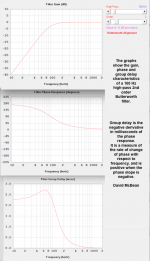
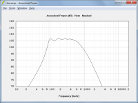
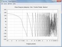
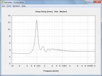
David,The attachments show the gain, phase and group delay characteristics of a 100 Hz high-pass 2nd order Butterworth filter.
Group delay is the negative derivative in milliseconds of the phase response. It is a measure of the rate of change of phase with respect to frequency, and is positive when the phase slope is negative.
Brilliantly succinct explanation and graphics!
As many don't understand how frequency response, phase and group delay relate to each other, it would be of interest to also show the comparative phase and group delay of a horn/driver that rolls off at 12dB per octave below 100 Hz.
Thanks,
Art
Attachments
it would be of interest to also show the comparative phase and group delay of a horn/driver that rolls off at 12dB per octave below 100 Hz.
If it was EQ'd flat then wouldn't it look exactly the same?
The attachments show the gain, phase and group delay characteristics of a 100 Hz high-pass 2nd order Butterworth filter.
Group delay is the negative derivative in milliseconds of the phase response. It is a measure of the rate of change of phase with respect to frequency, and is positive when the phase slope is negative.
How does its millisecond quantisation relate to the distortion of the start up transient that is also associated with group delay?
Last edited:
There's really no quantization and the group delay doesn't have to do anything with milliseconds specifically, I don't know why that was even stated. It's simply in time units and what that is, depends on the other units used. If everything is in base units, which it really should, the group delay will be in seconds. You can present it on any scale you want, that's completely irrelevant.
The transient shape is distorted by the phase distortion, i.e. deviation of the phase response from linear (straight line on linear scale), which is it same as a non-constant group delay or non-flat amplitude frequency response (for a minimum phase device like a horn).
The transient shape is distorted by the phase distortion, i.e. deviation of the phase response from linear (straight line on linear scale), which is it same as a non-constant group delay or non-flat amplitude frequency response (for a minimum phase device like a horn).
Last edited:
group delay doesn't have to do anything with milliseconds specifically, I don't know why that was even stated.
It was stated because the description I gave is the same as the one I use in the Hornresp Help file, and Hornresp expresses group delay in milliseconds.
Audio frequency group delay is traditionally given in milliseconds because it is the most numerically convenient unit to use when dealing with loudspeaker systems. For example, a group delay of 5 milliseconds becomes a more cumbersome value of 0.005, 5E-3 or 5 * 10 ^ -3 when expressed in seconds.
Radio frequency group delay is not normally expressed in seconds for the same reason.
The attached diagram may help explain the relationship between phase and GD from another perspective.
taken from:
ACOUSTICAL FUNDAMENTALS | Pro Audio Encyclopedia
taken from:
ACOUSTICAL FUNDAMENTALS | Pro Audio Encyclopedia
Attachments

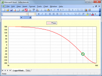
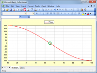
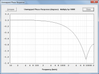
Phase wrap is just a compact way of displaying information. Once it is understood that it is NOT a 360 degree jump, confusion falls away, and the graph is clear.
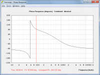
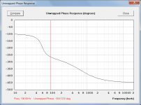
The first attachment shows a phase response wrapped between +/- 180 degrees. The second attachment shows the same phase response unwrapped.
Attachments
note that the logarithmic frequency scale will make even a perfectly linear phase response look bended
It is useful to keep the above in mind when comparing phase and group delay charts having logarithmic frequency scales.
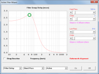
In the charts I posted earlier, the inflection point in the phase response appears to be at 100 Hz (see Attachment 1) whereas in the group delay chart it is calculated to be at 65 Hz (see Attachment 2). If the phase response was plotted using a linear rather than logarithmic frequency scale, then the phase inflection point would indeed be at 65 Hz, as identified and correctly shown in the group delay chart.
The example given in Attachments 3 and 4 shows how the phase response inflection point can appear to shift from its true frequency of 55 Hz to 70 Hz, when plotted using a logarithmic rather than a linear frequency scale. Note however, that even though the curve shape has changed and the inflection point has appeared to move, the phase values as plotted with respect to frequency nevertheless remain correct.
Attachments


it would be of interest to also show the comparative phase and group delay of a horn/driver that rolls off at 12dB per octave below 100 Hz.
Hi Art,
Example attached.
The unwrapped phase chart is correct up to 10 KHz. Above this frequency, the sampling rate is such that the phase unwrapping algorithm cannot identify individual wraps.
Kind regards,
David
Attachments
The attached diagram may help explain the relationship between phase and GD from another perspective.
To calculate group delay in milliseconds at frequency f:
Os = very small frequency offset value
f1 = f - Os
f2 = f + Os
Ph1 = phase shift in degrees at f1
Ph2 = phase shift in degrees at f2
Group delay at frequency f = (Ph1 - Ph2) / (2 * Os) * 1000 / 360 milliseconds
How does its millisecond quantisation relate to the distortion of the start up transient that is also associated with group delay?
Here you can read your hart out re: start up "delay / timing error".
My take is that when you leave a none (zero) signal condition and transition into a continuous (steady sate) one, there is burst of wide bandwidth content generated. What shall not be forgotten about this "burst" is that is:
- very short
- very low level (NB... from ZERO)
- non existent for the next zero passing as for this occasion, the signal is continuous i.e. do not contain the abrupt departure from zero which is a very special case and only happen once for every song on a CD (not really as the it is drown in the systems intrinsic noise 😉)
//
Hi Art,
Example attached. Post 8455
The unwrapped phase chart is correct up to 10 KHz. Above this frequency, the sampling rate is such that the phase unwrapping algorithm cannot identify individual wraps.
Kind regards,
David
Thanks.
Was not expecting the thousand+ degrees of phase rotation in the pass band, also appears that horn rolls off closer to 24dB per octave than 12.
If I recall correctly, applying a delay equal to the path length of the horn (or path length + one meter?) flattens the simulation's phase response over the flat amplitude region of the horn.
I should be asleep, up all night, 5:10 AM, better sign off ..
Last edited:
Or in layman's terms as this topic seems to keep going around in circles🙂 wish me luck...
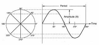
If it takes 1 Second (1000ms) to complete one full cycle (1Hz), to complete a quarter of a cycle would take a quarter of a second / 250ms.
A quarter of a turn is 90 degrees - 360/4 = 90.
If it takes 1/10th of a second (100ms) to complete one full cycle (10Hz), to complete a quarter of a cycle would take a quarter of a second / 25ms.
So
90 phase @ 1Hz = 250ms
90 phase @ 10Hz = 25ms
180 phase @ 1Hz = 500ms
180 phase @ 10Hz = 50ms
etc
so 90 degree phase lag at 10Hz would be equivalent to 25ms of group delay (GD)
etc etc etc.
Attachments
- Home
- Loudspeakers
- Multi-Way
- Is it possible to cover the whole spectrum, high SPL, low distortion with a 2-way?