Indeed, you have to use IIR filtering to copy a minimum phase analog filter.Hmm, I am not sure the FIR apporach is right to simulate a real-world analog filter. Does the phase response match? Usually, IIR filters are used to simulate analog filters, whereas FIRs don't have analog implementations.
FIR is phase linear, IIR is minimum phase.
As told its a IIR filter and one can load a IIR filter in a FIR engine or please read the miniDSP manual. That said i haven't miniDSP myself so can't test filter myself other than look up curves is alright looking into REW and that was why suggestion is to benchmark its electrical RCA output so that amp and tweeter don't get damaged, because by accident my settings for bin-file is wrong somewhere.
Its right FIR approach can be linear phase and what got most to think that uuuh then its always linear phase but FIR filters can manipulate both in amplitude and phase domain and if phase is set to follow amplitude as a minimum phase domain filter we have our analog filter replica or can we say IIR filter.
Its right FIR approach can be linear phase and what got most to think that uuuh then its always linear phase but FIR filters can manipulate both in amplitude and phase domain and if phase is set to follow amplitude as a minimum phase domain filter we have our analog filter replica or can we say IIR filter.
Byrtt,
My practical experience with digital processing is poor, so I am not well placed to give many comments on this.
Admit had using tons of time over in free Rephase that can do all the wonders be it IIR FIR or a mix, myself is then poor on miniDSP experience and what limitations or rules for those bin-files so will be happy if it works because then when guided how to do it then Matthias can output correction files himself in a few minutes for whatever new ideas or changes he can come up with to try out, and in understand yourself is in middle of a new build and lack of time should be a win win.
Ok, I played some music with the biquad filters from post 619 for a while. This is promising!
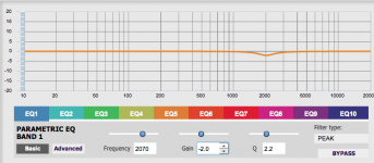
There is still a bit too much "energy" in the lower treble/midrange. I made some quick-n-dirty measurements (very messy overlays of many curves in the end, not very useful to show here) while I was trying to set an equalizer notch to reduce effect that my ears didn't like at the same time. In the end I could identify a small peak at about 2 to 2.1 kHz, which my ears didn't like. The corresponding notch settings are attached. I will have to make some proper measurements and then go back to the filter design, hoping I can change the transfer curve accordingly.
Apart from this, there is some internal resonances in the enclosure happening (as we figured out earlier by acoustic and impedance measurements). These resonances are audible, but surprisingly not as bad as one might expect from the massive peaks/dips around 400 Hz. I ordered some wool to stuff into the the enclosure, which I hope attenuates the resonances.
I also wondered how bad it would be to put the bass reflex port to the rear. The port outlet would be further away from the woofer, but the 400 Hz interferences would be attenuated quite a bit before they reach the ears.
Attachments
Before you even started making sawdust, I suggested careful placements of a few board pieces to break up the resonances visible in the software, and also covering the boards in dampening material.
Did you place some wool felt on top of the port and also sides next to woofer? Remember to leave the last 2-3cm close to beginning of port "naked".
Did you place some wool felt on top of the port and also sides next to woofer? Remember to leave the last 2-3cm close to beginning of port "naked".
Before you even started making sawdust, I suggested careful placements of a few board pieces to break up the resonances visible in the software, and also covering the boards in dampening material.
I know.

Did you place some wool felt on top of the port and also sides next to woofer? Remember to leave the last 2-3cm close to beginning of port "naked".
I have not put anything in there yet. I will try different dampening materials, and also the boards (although in previous projects the boards had surprisingly little effect).
... (although in previous projects the boards had surprisingly little effect).
It should work well, but they have to be angled just so, and at locations that break up the distances between reflective surfaces.
I'm thinking two boards going sidewall to sidewall, maybe 12mm ply is enough? both ca 12-18cm wide pending on angle and location.
For example: One behind the driver at ca 45 degrees reflecting sound upwards, the other a bit higher , maybe 15cm and slanted almost parallel, maybe a bit more forward than the lower. Cover the boards in felt.
You primarily want to emulate a longer distance to port, but there has to be sufficient air around the boards on all sides so they do not cause disturbances in the tuning.
Does it make sense or am I rambling?
Last edited:
It should work well, but they have to be angled just so, and at locations that break up the distances between reflective surfaces.
I'm thinking two boards ... Does it make sense
I probably does make sense, but I am not sure I get it. A drawing might be useful.
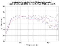
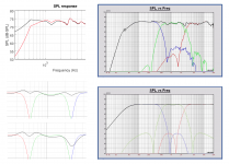
I made some more measurements (microphone 1m from baffle, height centered between mid and tweeter; SPL level not calibrated because this was measured without level calibration of the miniDSP + active amps). I believe it's better to forget about that peak/notch from post 625 for the moment. I think the mid/tweeter combination is doing really well.
The first attachment shows the on-axis SPL response of the full system. The black line was measured with woofer, midrange and tweeter connected at the same time. The red line was measured with the woofer disconnected. The woofer output obviously interferes with the midrange between 900 Hz and 2 kHz. This is not good, and we need to fix this somehow. Is this the leakage of the elliptic low pass filter of the woofer?
The second attachment shows the SPL measured at 0, ±30° and ±60° horizontal. I think the dispersion is nice and smooth, even at the x-over from the mid to the tweeter between 2 to 2.5 kHz. The two dips at 1.4 kHz and 2.5 kHz are attenuated in the off-axis curves, which confirms they are due to baffle-edge diffraction. I don't see anything to worry about in these curves.
I really think the woofer needs some work. It really shouldn't upset the midrange like it does. What are your thoughts about this?
Attachments
Looks like woofer and mid are not at same cycle, timing issue. Play only WM and increase delay to mid gradually check also with inverted polarity of mid. This is a really painstaking stage and you might need more delay than you think.... When it looks and sounds ok, check MT timing too. Then all three.
...The woofer output obviously interferes with the midrange between 900 Hz and 2 kHz. This is not good, and we need to fix this somehow. Is this the leakage of the elliptic low pass filter of the woofer?...
...I really think the woofer needs some work. It really shouldn't upset the midrange like it does. What are your thoughts about this?
Even using 100% clean slopes as the theoretical pure target shared by Paul show ripple summing spread over systems bandwidth and specific in that 1-2kHz area there is some interference for this particular filter setup, well even if all drivers had same center and AC as was it a perfect coxial there is still some small ripple but less than when they physical spaced apart as for Monkey Box. Thought is not much to do about it when 100% clean slopes is not perfect but in simulation it looks tweaked component version is little worse in that area than Pauls' original, other thought is guess many real world systems to be practical and cost effective have exactly same non ideal sum as compromise, other thought is above can be why many use symetrical LR filters because of non ripple smooth summing but will have to be simulated if works any good for physics of Monkey Box.
Last edited:
Looks like woofer and mid are not at same cycle, timing issue. Play only WM and increase delay to mid gradually check also with inverted polarity of mid. This is a really painstaking stage and you might need more delay than you think.... When it looks and sounds ok, check MT timing too. Then all three.
Adding some artificial delays will most certainly change the interference -- but it will not remove the issue, and it would be difficult to implement in the analog x-over.
Even using 100% clean slopes as the theoretical pure target shared by Paul show ripple summing spread over systems bandwidth and specific in that 1-2kHz area there is some interference for this particular filter setup, well even if all drivers had same center and AC as was it a perfect coxial there is still some small ripple but less than when they physical spaced apart as for Monkey Box. Thought is not much to do about it when 100% clean slopes is not perfect but in simulation it looks tweaked component version is little worse in that area than Pauls' original, other thought is guess many real world systems to be practical and cost effective have exactly same non ideal sum or compromise, other thought is above can be why many use symetrical LR filters because of non ripple smooth summing but will have to be simulated if works any good for physics of Monkey Box.
I don't think this issue is related to summing at the x-over frequency (about 400 to 500 Hz), which is much lower then the trouble area of about 1-2 kHz. Ideally, the woofer should be "silent" from 1 kHz and up.
I'd expect the woofer to be out of phase above the x-over frequency. Remember that the elliptic filters have "leaky" stop bands and the (unfiltered) woofer gets really loud between 1 and 3 kHz (about 100 dB-SPL or so). I wouldn't be surprised if the stop-band "leak" causes the midrange trouble at 1-2 kHz -- but I am not sure.
Would it make sense to try another filter function without "stop-band leakage" (Butterworth, Bessel, etc.) just to see if the issue goes away?
EDIT: take a look at the modelled acoustic output of the woofer at 1-2 kHz in post 619. It's only 24 dB below the midrange. Hmm.
Last edited:
...I don't think this issue is related to summing at the x-over frequency (about 400 to 500 Hz), which is much lower then the trouble area of about 1-2 kHz. Ideally, the woofer should be "silent" from 1 kHz and up.
I'd expect the woofer to be out of phase above the x-over frequency. Remember that the elliptic filters have "leaky" stop bands and the (unfiltered) woofer gets really loud between 1 and 3 kHz (about 100 dB-SPL or so). I wouldn't be surprised if the stop-band "leak" causes the midrange trouble at 1-2 kHz -- but I am not sure.
Would it make sense to try another filter function without "stop-band leakage" (Butterworth, Bessel, etc.) just to see if the issue goes away?
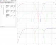
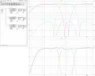
Below visuals show how the perfect text book slope would sum, the first one is using Monkey Box spacing of drivers and AC mismatch, the second one as a perfect coxial with same AC and no spacing. Guess mostly for other slopes symetrical or non symetrical than a pure symetrical LR we get some ripple interference here and there, if LR will work good for Monkey Box physicals and sum smooth as its theory is non known and has to be simulated.
Attachments
Last edited:
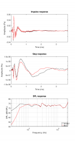
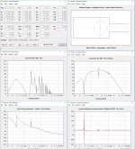
You guys can look at filters all you want, but the wiggles coincide pretty good with the expected internal resonances that come out through the port.
See that small spike on acoustic resonance at ca 250hz? often, but not always, that marks the beginning of trouble, it is the sole reason I suggested having the port further away from the woofer.
See that small spike on acoustic resonance at ca 250hz? often, but not always, that marks the beginning of trouble, it is the sole reason I suggested having the port further away from the woofer.
Attachments
Below visuals show how the perfect text book slope would sum, the first one is using Monkey Box spacing of drivers and AC mismatch, the second one as a perfect coxial with same AC and no spacing. Guess mostly for other slopes symetrical or non symetrical than a pure symetrical LR we get some ripple interference here and there, if LR will work good for Monkey Box physicals and sum smooth as its theory is non known and has to be simulated.
You guys can look at filters all you want, but the wiggles coincide pretty good with the expected internal resonances that come out through the port.
See that small spike on acoustic resonance at ca 250hz? often, but not always, that marks the beginning of trouble, it is the sole reason I suggested having the port further away from the woofer.
Guys, I am with you. But I believe I wasn't clear enough about what I was talking about. I was NOT talking about any issues at 500 Hz or below.
Take another look at the SPL curves in the first attachment of post 629. The black curve was measured WITH the woofer, the red curve was measured WITHOUT the woofer. You can see that WITH the woofer, the SPL is LOWER between 1-2 kHz. This must be some interference resulting from the woofer output in the 1-2 kHz range, which, according to the modelled curves in post 619 is only 24 dB below the midrange output in the 1-2 kHz range.
Last edited:
If this is timing issue, minidsp feeding 3 amplifiers will never behave exactly like a passive circuit driven from a single amp. We must also remember that some amps invert phase, some don't. So, I don't think same calculated delays work for both.
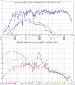
With minidsp 2x4HD you can change timing very delicately, by 0,01ms (10us, 3mm) steps. Above xo wavelength shortens and hickups come easier visible in measured response than below xo, where reflections mess up everything.
I am accustomed to LR symmetrical filters, I have tried duelund, first order, Bessel etc. and S.Harsch with minidsp and Hypex, but I just don't get them working and sounding right. Steep filters like LR48 are more forgiving to make response look right, but sound is eery instead of airy like with poor timing.
Kaffiman noticed perhaps the most obvious reason, reflex port resonances, have you measured the port mouth response? Backside port with 90¤ bend in the pipe might help. My Amphion Helium has backside port.
Attachments
Last edited:
This must be some interference resulting from the woofer output in the 1-2 kHz range, which, according to the modelled curves in post 619 is only 24 dB below the midrange output in the 1-2 kHz range.
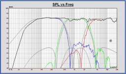
Yes, but with the tweaked woofer filter the outband reduction between 1 and 2 kHz is 5 dB worse than the original targets.
In the plot the SPL of the modified filter and the original targets.
I did see it while making the digital version of the tweaked filter, but I thought it was your idea to do the modification like that.
Maybe it is better to reduce the woofer outband conform the targets.
Of course a low pass LR4 at 500 Hz has more outband reduction above 1.2 kHz and about 18 dB more at 2 kHz and in phase with the midrange. But it is not elliptical...
Attachments
Can't stop thinking it has been there all the time simulation or not including if one use optimal textbook smooth responses and is inherent non ideal compromise to filter type even if we had not any AC timing plus spacing mismatch, some plot scales mask the fenomen but its there in all of them below.
Attachments
- Home
- Loudspeakers
- Multi-Way
- Open Source Monkey Box