simulation quad 6.5" woofers
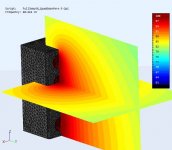
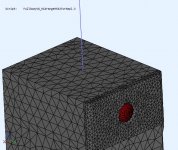
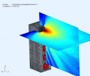
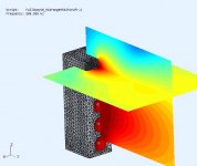
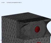
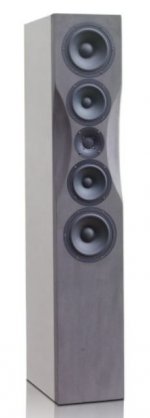
The simulation model can provide insight into the where and why of possible improvements. I already have an ABEC model of this arrangement (speaker sits on the IB floor, pic#1) modelling both the electrical (LR4 LP, driver model) and acoustic (driver membrane, rear chambers, case) components. The cabinet (model and actual) uses an R20mm round over on the side edges. The rear chamber uses moderate damping.
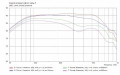
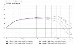
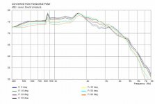
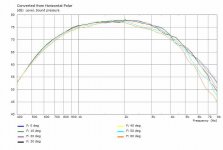
At 1m axial distance the woofer SPL varies a bit from floor (graph#1) but there are no floor bounce nulls. However as you move out from the speaker it evens out vertically (graph#2). I've measured this (earlier post) to confirm the model works properly. I also noticed this when I use different areas of this room from 1m-4m from the speaker.
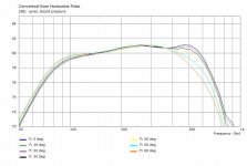
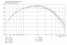
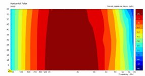
The horizontal polar curves (graph#3) are effected by the driver size, baffle width and round over radius. The baffle width (26cm) is 2x driver diameter (13cm). Based on the curves I don't see any point in modifying the woofer baffle to flattened the curves as they have very low ripple (1dB).
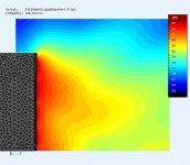
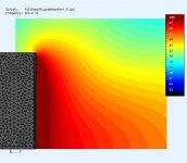
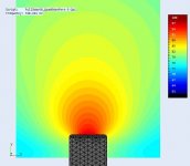
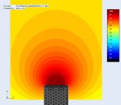
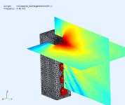
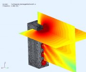
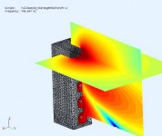
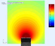
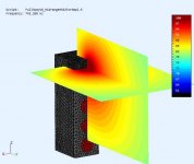
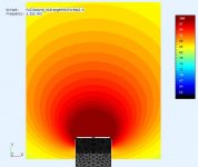
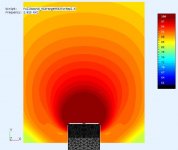
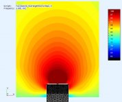
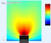
I added a few pics to show the horizontal and vertical fields and how they wrap around the cabinet.
The simulation model can provide insight into the where and why of possible improvements. I already have an ABEC model of this arrangement (speaker sits on the IB floor, pic#1) modelling both the electrical (LR4 LP, driver model) and acoustic (driver membrane, rear chambers, case) components. The cabinet (model and actual) uses an R20mm round over on the side edges. The rear chamber uses moderate damping.
At 1m axial distance the woofer SPL varies a bit from floor (graph#1) but there are no floor bounce nulls. However as you move out from the speaker it evens out vertically (graph#2). I've measured this (earlier post) to confirm the model works properly. I also noticed this when I use different areas of this room from 1m-4m from the speaker.
The horizontal polar curves (graph#3) are effected by the driver size, baffle width and round over radius. The baffle width (26cm) is 2x driver diameter (13cm). Based on the curves I don't see any point in modifying the woofer baffle to flattened the curves as they have very low ripple (1dB).
I added a few pics to show the horizontal and vertical fields and how they wrap around the cabinet.
Attachments
-
 Quad6Woofer-3Dfield@60Hz.jpg37.5 KB · Views: 402
 -
 Quad6Woofers-SPL-Vert@1m.jpg40.1 KB · Views: 399
 -
 Quad6Woofers-SPL-Vert@3m.jpg38.7 KB · Views: 396
 -
 Quad6Woofers-SPL-Hpolar@3m.jpg38.8 KB · Views: 392
 -
 Quad6Woofer-Vfield@750Hz.jpg39.1 KB · Views: 120
 -
 Quad6Woofer-Vfield@300Hz.jpg38 KB · Views: 690
 -
 Quad6Woofer-Vfield@100Hz.jpg36.7 KB · Views: 709
 -
 Quad6Woofer-Hfield@750Hz.jpg27.7 KB · Views: 118
 -
 Quad6Woofer-Hfield@300Hz.jpg27.4 KB · Views: 124
 -
 Quad6Woofer-Hfield@100Hz.jpg28.4 KB · Views: 399
Nice work
Thanks @adason.
We talked earlier about dome midranges with fabric/metal. I really enjoy the RS52AN, it's an excellent sounding midrange.
Your excellent results once more prove that with proper design and the proper processing tools it is possible to make a silk purse purse of a sow's ear audiowise.
Usually I do not care much for lowend distortion, but the results @30 Hz are just great.
Keep on trucking!
Eelco
Usually I do not care much for lowend distortion, but the results @30 Hz are just great.
Keep on trucking!
Eelco
Thanks @Boden.
It's interesting (and fun) trying to tell if a component or a configuration will give the best bang for the buck. I could be entertained for some time looking for silk 😀
It's interesting (and fun) trying to tell if a component or a configuration will give the best bang for the buck. I could be entertained for some time looking for silk 😀
midrange improvements
I was looking for a way to improve the midrange off axis performance. The ABEC model's polar response includes the LR4 BP.
The first pic#1 represents what I actually built. The dome is 50mm, baffle is 260mm, and R20 roundover. So the flat baffle is approx 5x the driver Sd. It's not bad (graph #1), I was just looking for an improvement.
The baffle "wart" (pic#2) could be made from 3 layers of 20mm wood routed seperately "round over -> chamfer -> cove" then glued to form the shape. The midrange mounting disc is large (120mm) so it limits what I can do (...and I'm not removing it). The shelf lip caused by the lower woofer cabinet is still causing some diffraction at higher freq (graph#2) but the trend is improvement. It justifies a few more passes at smoothing this out. The idea was inspired by the Revel Salon2.
Attachments

The 4x6.5 is more consistent (even) with distance, sounds cleaner and more detailed. The concept is good enough to invest in better woofers because these budget woofers start sounding muddy when pushed (>95dB@1m) which is OK for the test as I rarely play that loud.

A good woofer choice:
Anarchy 7 inch woofer by Denovo Audio
Non-linear as seen below.
You might also consider a change in tweeter:
SB Acoustics SB26ADC-C000-4 Aluminum Dome Tweeter
SB Acoustics SB26ADC-C000-4 | HiFiCompass
Attachments
Is it possible to render a polar map for the whole speaker in it's latest iteration, horizontal and vertical?
Hi Don,
Great Sim work and fantastic to explore the correlation between real-world measurements, Sims and perceived sound quality with listening tests... Great thread!
Please can you summarise your thoughts/conclusions so far?
Also, are you going to use dedicated subs below say 60Hz, or are the stand-alone speakers going to have be full range?
What are your target SPL's?
Thanks in advance.
A.
PS Pls find attached a sim for a great 8 inch driver I used in a small (7 litre) sealed box, active crossover to sub at 60Hz and to Beyma TPL at 1,800Hz... Sounded great! Now 4 of these in a miny array plus nice midrange and TPL up top... Wow!
Attachments
A good woofer choice:
Anarchy 7 inch woofer by Denovo Audio
Non-linear as seen below.
You might also consider a change in tweeter:
SB Acoustics SB26ADC-C000-4 Aluminum Dome Tweeter
SB Acoustics SB26ADC-C000-4 | HiFiCompass
Thanks for the driver suggestions. I'll be working on midrange for a while but I'll keep the suggestions in mind.
Is it possible to render a polar map for the whole speaker in it's latest iteration, horizontal and vertical?
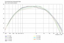
This is for 4x6.5" and the flat baffle midrange model. I use a LR4 BP XO and this is 4Pi space (no floor).
The Hpolar is 0-60deg there is a little variation as expected because there is very little beaming. The measurements are at midrange height @3m out, but these will vary based on where the "mic" is placed that's why I also like to look at the SPL fields. You can see diffraction and nulls off the woofer cones directed to the floor where (at these freq) can be absorbed by the carpet (but not in this model). There is a "sharp peak" (~805Hz) in the Hpolar due to limited samples in this freq range (3), it should be a bump with more samples.
Attachments
Hi Don,
Great Sim work and fantastic to explore the correlation between real-world measurements, Sims and perceived sound quality with listening tests... Great thread!
Please can you summarise your thoughts/conclusions so far?
Also, are you going to use dedicated subs below say 60Hz, or are the stand-alone speakers going to have be full range?
What are your target SPL's?
Thanks in advance.
A.
PS Pls find attached a sim for a great 8 inch driver I used in a small (7 litre) sealed box, active crossover to sub at 60Hz and to Beyma TPL at 1,800Hz... Sounded great! Now 4 of these in a miny array plus nice midrange and TPL up top... Wow!
I have to use subs for both woofer variants and for room issues. The sealed chamber woofers won't go low enough unless I used some extreme EQ (shelf) to force them flat. In the previous measurements I used a 12" BP6 but I also have a 10" BR to even out the room. It was a good exercise, as the floor is between me and the speaker and its the one item I can't seem to remove 🙂. The quad woofers minimizes the bounce problem and I can tell the difference even with budget woofers.
I would like to get 100dB @1m so that it would be in the 90dB's at one of my listening positions. So with speaker avg 90dB/w@1m I only need about 8w. I don't need PA levels, just clean and detailed.
That woofer was mentioned earlier by Scott and it looks good. I have up to 10L per chamber so I think I can get a good 6.5" woofer to reach 70Hz putting less demand on the subs.
Another attempt to improve the midrange dome H-polars. Some more blending to match the lower woofer case and upper tweeter case (not present) and remove the step.
The polar is getting smoother and the horizontal fields are looking better. There just a little field deformation near the upper XO (4.5Khz). It's getting closer to what I want.
.
The polar is getting smoother and the horizontal fields are looking better. There just a little field deformation near the upper XO (4.5Khz). It's getting closer to what I want.
.
Attachments
-
 Hfield@750Hz.jpg28.3 KB · Views: 116
 -
 Hpolar@3m.jpg38.5 KB · Views: 123
 -
 HpolarContour@3m.jpg24.6 KB · Views: 106
 -
 Fields@750Hz.jpg33.4 KB · Views: 142
 -
 3Dperspective.jpg69.6 KB · Views: 134
 -
 Hfield@1K2Hz.jpg29.6 KB · Views: 102
 -
 Hfield@2KHz.jpg29.4 KB · Views: 93
 -
 Hfield@3KHz.jpg29.3 KB · Views: 103
 -
 Hfield@4K5Hz.jpg29.4 KB · Views: 104
Another attempt to improve the midrange dome H-polars. Some more blending to match the lower woofer case and upper tweeter case (not present) and remove the step.
The polar is getting smoother and the horizontal fields are looking better. There just a little field deformation near the upper XO (4.5Khz). It's getting closer to what I want.
.
How cool is that! Very good simulating skills you've got. Could you sometime write a tutorial for how to get started to do sims of an speaker enclosure? Or is there already some tutorials somewhere available?
..Could you sometime write a tutorial for how to get started to do sims of an speaker enclosure? Or is there already some tutorials somewhere available?
 +1
+1-a good place for it (as opposed to a thread):
diyAudio - Article
Another attempt to improve the midrange dome H-polars. Some more blending to match the lower woofer case and upper tweeter case (not present) and remove the step.
I quite like the scallop on the DXT-WAVE
Heissmann Acoustics | DXT-Wave | d appolito tower speaker
Some information here on how it was made
Diskussion zur DXT-Wave von Alexander Heissmann
Attachments
How cool is that! Very good simulating skills you've got. Could you sometime write a tutorial for how to get started to do sims of an speaker enclosure? Or is there already some tutorials somewhere available?
Thanks.
There are 3 main tools used [FreeCad, Gmsh, ABEC] to create the mechanical part, mesh the design, then build and solve the model. There are some basic tutorials/demos for using ABEC that are provided by it's vendor RandD Team. I don't know of an instructional tutorial to explain the entire design flow for a multiway speaker. I have been asked to make a tutorial, I'm still considering it (lots of work and support), but I'm not sure how much interest there would be. You don't see much ABEC used in this forum. It can be steep learning curve but ABEC is a really fantastic tool. Once you acclimatize to it, any design becomes possible 🙂
There is some great info from @Gaga on using Gmsh into ABEC at ABEC experts - help! that might help.
A good idea as threads tend to fill up, then are hard to follow as they meander. I'm still not ready to create it 🙂
I quite like the scallop on the DXT-WAVE
Some information here on how it was made
Diskussion zur DXT-Wave von Alexander Heissmann
Hi Fluid,
A good idea, thanks for the link. The scallop would provide the needed reduced baffle width at the dome. I would like to limit Z=14cm for my midrange section. A scallop would also be easy to fabricate. It's worth a try, lets see what it does. Should have something tomorrow.
..I'm still not ready to create it 🙂
Boooo! BOOOOOOOOOOOO! 😛 😀
-and besides, you should have plenty of covid.. er, LEISURE-TIME available.
- Home
- Loudspeakers
- Multi-Way
- Modular active 3 way - work in progress