If there is a bit of interest here perhaps starting a new thread may be wise.
It doesn't look as if my suggestion of a geometrically simple speaker test case has picked up much if any support in this thread (which I assume it is getting looked at by most with an interest in the numerical simulation of speakers). It doesn't make sense as a solo effort and so perhaps later when more DIY folk rather than just the industry are using BEM/FEM simulations in their designs.
Mesh 4 Comparisons
Back in post #118 where this all started, there was as interest in comparing design flows to get a mesh into ABEC3. A simpler way.
I've changed the options a little after playing with the tools. There is no benefit to bringing stl into GMSH because its a mesh-mesh conversion.
a) use Freecad Std mesh stl to ABEC and remesh if required
b) use Freecad Mefisto mesh stl to ABEC and remesh if required
b) use Freecad stp to GMSH msh then to ABEC and remesh if required
There was also the issue of specifying ABEC3 "MeshFrequency" or "EdgeLength" as required in the control solver. It's related to the quality of the simulation's upper freq and can result in an ABEC remesh if it's insufficient. In the ABEC3 help document, the relationship is specified as "EdgeLength=0.5*c/MeshFrequency" where c~344m/s. The FreeCad mefisto stl algorithm can specify edge length, so 20mm edge -> 8600Hz and 30mm edge -> 5733Hz before triggering ABEC remeshing.
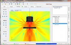
I set the mesh parameters to provide approx 2000 element meshes to allow a fair comparison between the algorithms. What is interesting, in the table below, is the dramatic jump in #elements when the imported mesh is too coarse for the specified MeshFrequency and a remesh is triggered. The HAT is aimed at the test disc and the diffraction patterns should be very similar if the mesh surfaces are adequate. My preferred design path will be FreeCad stl direct to ABEC as I can get as good results (as GMSH) with fewer steps. I will also correct a statement I made earlier in post #102, you actually do need to create the 1/4 symmetry mesh before importing into ABEC.
The pictures are :
1) freecad mefisto stl 20mm edge ABEC meshfreq 8Khz and obs 3.6Khz
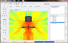
2) freecad mefisto stl 30mm edge ABEC meshfreq 4Khz and obs 3.6Khz
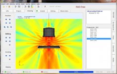
3) freecad std stl 0.94mm and 30deg dev ABEC meshfreq 4Khz and obs 3.6Khz
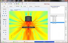
4) freecad stp GMSH delaunay 0.33 size ABEC meshfreq 4Khz and obs 3.6Khz
5) mesh comparisons
Back in post #118 where this all started, there was as interest in comparing design flows to get a mesh into ABEC3. A simpler way.
I've changed the options a little after playing with the tools. There is no benefit to bringing stl into GMSH because its a mesh-mesh conversion.
a) use Freecad Std mesh stl to ABEC and remesh if required
b) use Freecad Mefisto mesh stl to ABEC and remesh if required
b) use Freecad stp to GMSH msh then to ABEC and remesh if required
There was also the issue of specifying ABEC3 "MeshFrequency" or "EdgeLength" as required in the control solver. It's related to the quality of the simulation's upper freq and can result in an ABEC remesh if it's insufficient. In the ABEC3 help document, the relationship is specified as "EdgeLength=0.5*c/MeshFrequency" where c~344m/s. The FreeCad mefisto stl algorithm can specify edge length, so 20mm edge -> 8600Hz and 30mm edge -> 5733Hz before triggering ABEC remeshing.
I set the mesh parameters to provide approx 2000 element meshes to allow a fair comparison between the algorithms. What is interesting, in the table below, is the dramatic jump in #elements when the imported mesh is too coarse for the specified MeshFrequency and a remesh is triggered. The HAT is aimed at the test disc and the diffraction patterns should be very similar if the mesh surfaces are adequate. My preferred design path will be FreeCad stl direct to ABEC as I can get as good results (as GMSH) with fewer steps. I will also correct a statement I made earlier in post #102, you actually do need to create the 1/4 symmetry mesh before importing into ABEC.
The pictures are :
1) freecad mefisto stl 20mm edge ABEC meshfreq 8Khz and obs 3.6Khz
2) freecad mefisto stl 30mm edge ABEC meshfreq 4Khz and obs 3.6Khz
3) freecad std stl 0.94mm and 30deg dev ABEC meshfreq 4Khz and obs 3.6Khz
4) freecad stp GMSH delaunay 0.33 size ABEC meshfreq 4Khz and obs 3.6Khz
5) mesh comparisons
Attachments
-
 freecad stl mefisto edge 20mm fmesh8K @3.6Khz .jpg193.9 KB · Views: 245
 -
 freecad stl mefisto edge 30mm fmesh4K @3.6Khz .jpg196.9 KB · Views: 239
 -
 freecad stl std 0.94mm 30deg fmesh4K @3.6Khz .jpg198.1 KB · Views: 237
 -
 gmsh delaunay 0.33size fmesh4K @3.6Khz.jpg200.5 KB · Views: 231
 -
 MeshCompare -5r.jpg120.9 KB · Views: 242
Last edited:
I've changed the options a little after playing with the tools. There is no benefit to bringing stl into GMSH because its a mesh-mesh conversion.
a) use Freecad Std mesh stl to ABEC and remesh if required
b) use Freecad Mefisto mesh stl to ABEC and remesh if required
b) use Freecad stp to GMSH msh then to ABEC and remesh if required
You should never remesh in ABEC if you have curved surfaces such as a waveguide because the new vertices will lie on the old big flat triangle and not the curved surface of the waveguide. Only consider remeshing in ABEC if all the surfaces are flat.
An STL mesh that is being produced for 3d printing will have the largest triangles possible on flat surfaces because these are exact if all you are interested in resolving is the geometry. This is not the case when solving for a sound field which may vary strongly over geometrically flat surfaces. Your STL meshes shown earlier suffered from this problem.
There was also the issue of specifying ABEC3 "MeshFrequency" or "EdgeLength" as required in the control solver. It's related to the quality of the simulation's upper freq and can result in an ABEC remesh if it's insufficient. In the ABEC3 help document, the relationship is specified as "EdgeLength=0.5*c/MeshFrequency" where c~344m/s. The FreeCad mefisto stl algorithm can specify edge length, so 20mm edge -> 8600Hz and 30mm edge -> 5733Hz before triggering ABEC remeshing.
Required mesh resolution is conventionally given by a number of elements per wavelength. 0.5*c/f is 2 elements per wavelength and only full spectral methods will produce accurate results with this level of resolution. I think ABEC uses zero order triangles which is the least accurate element and so will need significantly more elements per wavelength to give accurate results. It is easy to test this by doubling the refinement and checking if the result is the same or different. If it is the same then the coarser level of refinement is adequate. If it is different then the finer level of refinement may or may not be adequate and you will need to test again with another twice as refined grid. This method to find what level of grid refinement is required for grid independent solutions will be performed by all competent engineers when faced with a new numerical solver and/or new test case.
The number of elements per wavelength is not the only criteria for refinement. How strongly a surface curves also needs to be considered or else a small rounded shape will become rectangular or even completely flat. An example of this is the tweeter surround. Most mesh generators will have something to control this, often a maximum angle, but I am unfamiliar with freecad and gmsh. Is this present?
Are my comments like this useful to anyone?
You should never remesh in ABEC if you have curved surfaces such as a waveguide because the new vertices will lie on the old big flat triangle and not the curved surface of the waveguide. Only consider remeshing in ABEC if all the surfaces are flat.
An STL mesh that is being produced for 3d printing will have the largest triangles possible on flat surfaces because these are exact if all you are interested in resolving is the geometry. This is not the case when solving for a sound field which may vary strongly over geometrically flat surfaces. Your STL meshes shown earlier suffered from this problem.
FreeCad's "standard" stl can produce large triangles on flat surfaces. However the "mefisto" stl produces elements constrained by the max edge length. The mefisto max length can be used to deterministicaly generate a mesh consistent with ABEC3 MeshFrequency. Post #134 shows the mesh outputs of FreeCad's various stl export settings.
Required mesh resolution is conventionally given by a number of elements per wavelength. 0.5*c/f is 2 elements per wavelength and only full spectral methods will produce accurate results with this level of resolution. I think ABEC uses zero order triangles which is the least accurate element and so will need significantly more elements per wavelength to give accurate results. It is easy to test this by doubling the refinement and checking if the result is the same or different. If it is the same then the coarser level of refinement is adequate. If it is different then the finer level of refinement may or may not be adequate and you will need to test again with another twice as refined grid. This method to find what level of grid refinement is required for grid independent solutions will be performed by all competent engineers when faced with a new numerical solver and/or new test case.
The mesh vs frequency relationship is consistent with ABEC3 docs. You can certainly use mesh iterations to find an adequate result, but why not start by directly specifying the resolution you need. ? I also don't know enough of ABEC's internal working to be confident in tricking it by specifying a low MeshFrequency to avoid remesh. I check the solve report and I know in <10sec if the mesh if too coarse from seeing the jump in the #elements as I increase MeshFrequency.
I also think there are limited areas like waveguide throats and membranes where you may need an excessively high resolution to maintain a smooth surface to get a good results. I just don't have enough expertise to be intuitive about it.
The number of elements per wavelength is not the only criteria for refinement. How strongly a surface curves also needs to be considered or else a small rounded shape will become rectangular or even completely flat. An example of this is the tweeter surround. Most mesh generators will have something to control this, often a maximum angle, but I am unfamiliar with freecad and gmsh. Is this present?
Are my comments like this useful to anyone?
Yes, depending on the mesh generator you can specify edge length, or surface deviation and angle resolution. I agree there is more than #elements and element edge size to get a good result. When the mesh is generated I ask "does that look right" compared to the original solid. I'll still need to read some more and digest the idea of a "figure of merit" for mesh quality.
Yes, of course your comments are useful. This thread is very niche, and laying down information may help or inspire others to use these tools. It certainly improved my knowledge of meshes. Maybe the title should have included 'free beer"

Last edited:
...Are my comments like this useful to anyone?
Yes, very, as are Don's, Christoph's and others.
I don't want to clutter the thread with too frequent repetitions of "thank you, that's very informative" but I really appreciate all the comments.
Hopefully I can contribute a bit more in future, at the moment all I have is questions.
Best wishes
David
Back in post #118 where this all started, there was as interest in comparing design flows to get a mesh into ABEC3. A simpler way.
I've changed the options a little after playing with the tools. There is no benefit to bringing stl into GMSH because its a mesh-mesh conversion.
a) use Freecad Std mesh stl to ABEC and remesh if required
b) use Freecad Mefisto mesh stl to ABEC and remesh if required
b) use Freecad stp to GMSH msh then to ABEC and remesh if required
There was also the issue of specifying ABEC3 "MeshFrequency" or "EdgeLength" as required in the control solver. It's related to the quality of the simulation's upper freq and can result in an ABEC remesh if it's insufficient. In the ABEC3 help document, the relationship is specified as "EdgeLength=0.5*c/MeshFrequency" where c~344m/s. The FreeCad mefisto stl algorithm can specify edge length, so 20mm edge -> 8600Hz and 30mm edge -> 5733Hz before triggering ABEC remeshing.
I set the mesh parameters to provide approx 2000 element meshes to allow a fair comparison between the algorithms. What is interesting, in the table below, is the dramatic jump in #elements when the imported mesh is too coarse for the specified MeshFrequency and a remesh is triggered. The HAT is aimed at the test disc and the diffraction patterns should be very similar if the mesh surfaces are adequate. My preferred design path will be FreeCad stl direct to ABEC as I can get as good results (as GMSH) with fewer steps. I will also correct a statement I made earlier in post #102, you actually do need to create the 1/4 symmetry mesh before importing into ABEC.
The pictures are :
1) freecad mefisto stl 20mm edge ABEC meshfreq 8Khz and obs 3.6Khz
2) freecad mefisto stl 30mm edge ABEC meshfreq 4Khz and obs 3.6Khz
3) freecad std stl 0.94mm and 30deg dev ABEC meshfreq 4Khz and obs 3.6Khz
4) freecad stp GMSH delaunay 0.33 size ABEC meshfreq 4Khz and obs 3.6Khz
5) mesh comparisons
If you import an STL into ABEC, how do you select the surface faces?
I've been using GMSH to define what the faces are.
If GMSH isn't in the workflow, how do I know what the numbers of the faces are?


There is no benefit to bringing stl into GMSH because its a mesh-mesh conversion.
a) use Freecad Std mesh stl to ABEC and remesh if required
I read this as:
Fusion 360 stl (meshmixer) to ABEC and remesh if required.
-btw, there is also Salome in case you want something with the mesh sophistication of GMESH (..with plug-ins, note both "internal" and "external" algorithm's for meshes):
Mesh — SALOME Platform
If you import an STL into ABEC, how do you select the surface faces?
I've been using GMSH to define what the faces are.
If GMSH isn't in the workflow, how do I know what the numbers of the faces are?
I agree with your comments on GMSH, but everytime you make a design change the face numbering may change and its' just a list of nodes and elements that you need to interpret.
Based on the last trials I know it's possible to get sufficient quality stl's from FreeCad. I would like to export several stl files, from a single design, that are each associated with a single ABEC element. So I can import the stl mesh filename and map it to an element by name. Test case in about 1wk.
The elements and nodes need to be placed in various groups in order to apply boundary conditions. For example, a group for the tweeter cone on which to apply a velocity boundary condition which is the scalar product of the surface normal and the axial velocity of the voice coil. A group for the surround where this velocity component is scaled from the full voice coil velocity at the inner radius down to zero at the outer radius. A group for the cabinet surface which may be zero velocity or possibly the velocity from a simulation of the cabinet motion.I agree with your comments on GMSH, but everytime you make a design change the face numbering may change and its' just a list of nodes and elements that you need to interpret.
Can Freecad group surface elements and/or nodes in a form which ABEC recognises? I know gmsh can group the elements because their odd use of language to do it came up in discussion a few years ago. But does ABEC recognise these groups?
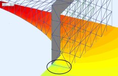
I am familiar with BEM but not ABEC. According to the presentation this example seeks to incorporate an infinite baffle into the boundary conditions which is a nice feature for modelling speakers. Unlike the symmetry boundary condition this boundary condition is almost certainly not exact (note to self: find out a bit more about ABEC) and so will likely produce artifacts like that shown.Here is a clip from the ABEC examples, the Expo 400 horn.
After it is solved there is small but noticeable artifact at the boundary, circled in the picture.
How do we eliminate or minimize this?
If you add another row to the infinite baffle grid I would expect this artifact to reduce in strength 1) because the field is weaker and 2) possibly because the approximation of the infinite baffle is improved but I don't know and would like to. If you do add another row to test can you please post the result.
The download and install is simple, I expected the usual problems, there always seems to be some issues, but it was completely trouble free.I am familiar with BEM but not ABEC...(note to self: find out a bit more about ABEC)
So don't hesitate, it took only minutes, it would be even more helpful to have your comments if you could reproduce results and experiment too.
This is just the untouched demo, I don't plan to modify much until I acquire a new computer.If you do add another row to test can you please post the result.
In the meantime I want to understand how the demos use boundary conditions (with sub domains) and infinite baffles.
As DonVK noted - there are examples but little explanation, you have to try to deduce their rationale.
Best wishes
David
Last edited:
The download and install is simple, I expected the usual problems, there always seems to be some issues, but it was completely trouble free.
So don't hesitate, it took only minutes, it would be even more helpful to have your comments if you could reproduce results and experiment too.
I don't work in windows and the version of wine on my desktop does not seem to be installed properly. Since I don't have a current need to use any windows programs when working I have delayed sorting it out until I upgrade to the current version of the platform when it will likely fix itself since I am currently doing one or two nonstandard things that have become standard on the current version of the platform. I have been waiting until all my important programs are known to run on the current version of the platform but having just checked the last one has been released and so I can now upgrade possibly next weekend. It is hard work preventing necessary software maintenance absorbing too much time.
Anyway, I will likely give ABEC a brief look in a week or twos time but it is fairly expensive, doesn't run on my work platform, cannot be integrated with other solvers or patched/fixed, lacks normal linear, quadratic and higher elements (reduces number of elements per wavelength), lacks a fast multipole implementation (allows solutions on larger grids),... Unlike FEM all the free BEM software I am aware of has limited general engineering use and so I am contemplating taking a couple of weeks in the summer to write some code.
Anyway, I will likely give ABEC a brief look in a week or twos time but it is fairly expensive...
The free demo version is fully capable, except for the inability to save solutions.
This turns out to be not a problem, just solve and do whatever you want, at worst re-solve if you revisit the work.
I expect it's limitations will become more obvious as I learn and use it more, but even that exploration process is educational.
I have just started to learn and appreciate some of the mathematical subtleties you mention but they haven't impacted me yet.
So ABEC is pretty satisfactory for free software, despite the consequences of lack of source code.
I look forward to when you have it, and to your own code.
Best wishes
David
lacks a fast multipole implementation
This is what I asked Andreas about back in post #72 , if I understand correctly?
Last edited:
The inability to post process results or integrate the solver with other software is a serious problem for getting work done efficiently. Which is of course the point. If you want to use ABEC to do work then you will need to buy a license. The demo version allows you determine if it will do what you want first which is good. I like the arrangement and the price doesn't look out of step with similar specialised engineering code given the small number of potential customers and the price of good quality general purpose BEM code without the extra bits for speakers.The free demo version is fully capable, except for the inability to save solutions.
This turns out to be not a problem, just solve and do whatever you want, at worst re-solve if you revisit the work.
This is what I asked Andreas about back in post #72 , if I understand correctly?
No I don't think so. Andreas seemed to be talking about what happens when evaluating the field inside the body and not outside. Source superposition, if I understand correctly which I may not, is likely an approach that avoids issues with the solution being unknown at the internal resonant frequencies of the body.
With standard BEM every node is influenced by every other node and the numerical problem rapidly becomes too large to handle on even moderately fine grids. Fast multipole is a method of approximating the small influence on an element of the elements that are not in it's near field in order to make the computation smaller and faster. It is not particularly relevant for most research BEM codes which tend to be used for modest sized problems but it is relevant for commercial codes used for engineering purposes.
Source superposition, if I understand correctly which I may not, is likely...
The discussion of source superposition in Rick's thesis is Section 4.2.4 and starts on P. 97. here > https://digital.library.adelaide.edu.au/dspace/bitstream/2440/41350/9/01front.pdf <.
Rick's reference is "Koopmann and Fahnline" https://asa.scitation.org/doi/10.1121/1.398450
Different from your description of fast multipole, but possibly some similarity between the approaches.
Do you have a reference for fast multipole that you recommend?
Best wishes
David
Last edited:
The discussion of source superposition in Rick's thesis is Section 4.2.4 and starts on P. 97. here
Thanks for the link (my quick google earlier failed) and it uses the principle I was expecting. It is close or possibly the same as the equivalent source method (and possibly multiple other similar sounding methods!).
Different from your description of fast multipole, but possibly some similarity between the approaches.
Yes.
I have never implemented it or researched the topic and so cannot distinguish useful references from the less useful. I understand the principle it is based on which is widely used in acoustics and other areas of physics. I am also aware that it is implemented in pretty much all good engineering BEM codes these days.Do you have a reference for fast multipole that you recommend?
It is a technique that approximates a BEM (or BEM-type) numerical representation in order to obtain a smaller numerical problem to solve. I would expect there to be a fair amount of practical knowledge about what works well in what circumstances which commercial companies are likely to keep fairly close to themselves in order to add value to their products.
It is a technique that approximates a BEM (or BEM-type) numerical representation in order to obtain a smaller numerical problem to solve...
Ok, a quick search turned up a few references ~1,000,000 D.of Freedom solved on a PC (!)
I was happy with ABEC until I saw this, now I understand your attitude better.
Thanks for the information, even if it's made me jealous.
Best wishes
David
Found some fast multipole software.
There's a free student version but it's limited to "only" 20,000 DoF.
Last edited:
- Status
- This old topic is closed. If you want to reopen this topic, contact a moderator using the "Report Post" button.
- Home
- Loudspeakers
- Multi-Way
- ABEC experts - help!