For comparison's sake, here's how I did my sims:
1), 2) 3) 4)
5) Import the mesh file into ABEC.
As a workflow solution that kind of sucks. 😱
One of things I don't like is GMSH and altering the original CAD file (and its limitations) where GMSH alters the (likely step/stp file) to an openCascade form.
This is that "on-the-fly" model alteration for adjustments in the resulting mesh. Beyond the limitations of what you can actually do, the interface just isn't like a modern CAD, and certainly isn't anywhere near as intuitive as Fusion 360. Plus, do you really want to learn to do that? I don't.
What would be ideal is Fusion 360 (model + mesh export) > ABEC3 - that's it. 🙂
Note that Meshmixer (engine) is integrated into Fusion 360. (..see YouTube video below.)
I guess what I'm really asking here is:
-what does it require to get a good *stl. file for ABEC3? (..and specifically from Fusion 360.)
*(..in that Fusion 360 does not output any other mesh format that ABEC3 accepts.)
YouTube
Last edited:
Symmetry
I've been playing around with symmetry in ABEC, trying to minimize my CAD work.
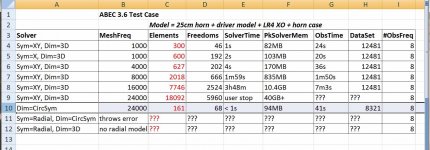
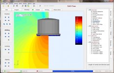
You don't have to create 1/4 symmetry mesh to use 1/4 symmetry solving in ABEC. I created a full box (but X!=Y) and setup both 1/4 and 1/2 symmetry solves to check the #elements and time used. As long as the mesh is positioned symmetric on an axis by either your CAD dwg or latter by using ABEC's shift/rotate (to move it) you will benefit from the symmetry. It's confusing at first because ABEC does not display the symmetry "cut" mesh when a full mesh is imported.
I've included an ABEC screen shot with symmetry display off, and notice the hat is shown in 1/4 symmetry. Both items actually used 1/4 sym in the solver, saving elements and time. 🙂
I've been playing around with symmetry in ABEC, trying to minimize my CAD work.
You don't have to create 1/4 symmetry mesh to use 1/4 symmetry solving in ABEC. I created a full box (but X!=Y) and setup both 1/4 and 1/2 symmetry solves to check the #elements and time used. As long as the mesh is positioned symmetric on an axis by either your CAD dwg or latter by using ABEC's shift/rotate (to move it) you will benefit from the symmetry. It's confusing at first because ABEC does not display the symmetry "cut" mesh when a full mesh is imported.
I've included an ABEC screen shot with symmetry display off, and notice the hat is shown in 1/4 symmetry. Both items actually used 1/4 sym in the solver, saving elements and time. 🙂
Attachments

As a workflow solution that kind of sucks. 😱
What would be ideal is Fusion 360 (model + mesh export) > ABEC3 - that's it. 🙂
<snip>
I guess what I'm really asking here is:
-what does it require to get a good *stl. file for ABEC3? (..and specifically from Fusion 360.)
*(..in that Fusion 360 does not output any other mesh format that ABEC3 accepts.)
ABEC 3.6 can import STL from FreeCAD. I just tried it. It will even "remesh" it when you change MeshFrequency parameter.
As a workflow solution that kind of sucks. 😱
It's not as bad as it sounds. I can run through all those steps in about 30-45 minutes for one model. I've tried a bunch of 3D programs but I just like 123D the best.
I can make an OS waveguide in about 5-10 minutes in 123D, but a lot of my crazy complex designs literally take 20-40 hours to design. I do a lot of Unity horns and the thing that sucks up all the time is:
1) making sure everything is correct. I've never had a 3D print where my drivers didn't line up; I put a lot of time into double checking that all the measurements are right.
2) The bane of my existence is drawing bolt holes. In a Unity horn, there's something like twenty bolt holes, and the depth of the holes varies. Drawing them one by one by one is a huge time killer. I'm always tempted to epoxy the woofers right onto the horn, but I hate the idea of wasting $10 if the design doesn't work!
Two Liter Unity Horn
This is an example of a design that took about 30-40 hours to create.
2) The bane of my existence is drawing bolt holes.
..oh god, bolt holes. 😱
I'm doing that crap by hand (drill) without a drill press (or a plunge router) for 5x 85 pieces for home theater chair isolation ("legs"). (..so the energy from the bass shakers I'm installing don't "sink"/transmit to the floor.)
-it's not going well, my pitiful homebrew jig for this is ..bad. 😀
(..I really should get a cheap CNC machine.. or maybe a 3d printer, but I'm still waiting for build volume to get better on cheaper sla/lcd resin printers.) 😱
ABEC 3.6 can import STL from FreeCAD. I just tried it. It will even "remesh" it when you change MeshFrequency parameter.
-well I knew that it accepted stl files. It just seems that "common wisdom" requires msh files. (..and I'm not sure why.) 😱 😱
I also played with symmetry models...[no sym = 8000, 1/2 sym =4000, 1/4 sym=2000, polar sym =?] elements. Not a surprise, as its what you'd expect.
So have you played with rotational symmetry yet?
How is it handled and how does it compare with Axidriver?
Best wishes
David
OK, checked the help file and now understand circular symmetry better.
Last edited:
-well I knew that it accepted stl files. It just seems that "common wisdom" requires msh files. (..and I'm not sure why.) 😱 😱
The game is the best representation for the fewest elements.
The only control I have with STL is step size. Using the same curvy part, only changing the resolution, results in [0.1mm res -> 12K elements], [0.5mm res ->4K elements], [1mm res ->1.5K elements]. A STEP -> MSH using GMSH can generate a good mesh with 300 elements. Other meshing programs may do even better.
So have you played with rotational symmetry yet?
How is it handled and how does it compare with Axidriver?
Best wishes
David
OK, checked the help file and now understand circular symmetry better.
I've never used AxiDriver so can't comment on relative performance.
I intended to include my polar (circular) test case in the last symmetry table, but I'm having problems with ABEC throwing exceptions and I don't know why yet. Maybe later tonight.
Last edited:
The only control I have with STL is step size.
Is this "control" you have with ABEC3? If so, what extra control does a msh file have with ABEC3? 😕
^@ScottG : my bad, my reply was ambiguous.
In Freecad, if I create mesh (stl), I have the option to select "standard" or "mefisto" algorithms as well as parameter "surface deviation" [my test case stated 1mm, 0.5mm. 0.1mm resolution].
In Freecad when I export as (stp) I have no options or parameters. Maybe they are buried. I'm a novice at Freecad.
In ABEC, after I import the meshed object, I have a parameter "mesh frequency". ABEC remeshes the object such that the elements are small enough to support that frequency. However, it seems to do so by subdividing the existing elements. ABEC allows you to select meshing algorithms options (Bifur, Delaunay) but they seem to effect only native objects, not the imported meshes.
Symmetry 2
Had a chance to run a circular (polar) symmetry model using the same hat as the previous tests. The circular symmetry results are added to the updated table below with the 1/4 (XY) and 1/2 (X) symmetry models.
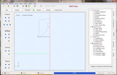
It's astonishing how much faster the model runs with circular symmetry. I only included the 24K mesh frequency because even that was fast. A "line" is required to describe the horn contour, and that could be done in a spreadsheet. The only oddity is the model's polar axis is the "X-axis" whereas the 1/n symmetry uses the "Z-axis". There are just minor output differences between symmetry models.
I don't have a radial symmetric model and don't intend on making one as I don't see the benefit at this point. There doesn't seem to be a way to describe the radial symmetry (#occurances/360, or angle, etc). I also think it would be a problem to create a radial model.
Had a chance to run a circular (polar) symmetry model using the same hat as the previous tests. The circular symmetry results are added to the updated table below with the 1/4 (XY) and 1/2 (X) symmetry models.
It's astonishing how much faster the model runs with circular symmetry. I only included the 24K mesh frequency because even that was fast. A "line" is required to describe the horn contour, and that could be done in a spreadsheet. The only oddity is the model's polar axis is the "X-axis" whereas the 1/n symmetry uses the "Z-axis". There are just minor output differences between symmetry models.
I don't have a radial symmetric model and don't intend on making one as I don't see the benefit at this point. There doesn't seem to be a way to describe the radial symmetry (#occurances/360, or angle, etc). I also think it would be a problem to create a radial model.
Attachments
Had a chance to run a circular (polar) symmetry model...
That is very informative, thanks that you followed it up.
Obviously a circular symmetry will be simpler but that difference is dramatic.
So if I stick to circular symmetry I don't need an AMD Threadripper after all.
But the whole point of my interest in ABEC is to look at the horn/woofer interaction and see how to improve it with non round horns, so it looks like I am still up for a new machine.
This convention is common, so you have to pick whether to have internal inconsistency or be inconsistent with most of the literature.The only oddity is the model's polar axis is the "X-axis" whereas the 1/n symmetry uses the "Z-axis".
Sometimes the physicist convention is different from the mathematician's, I hate that.
Best wishes
David
Last edited:
..so it looks like I am still up for a new machine.
-or wait the additional time (..likely starting the sim before bed-time and then checking on it in the morning). 😉
In ABEC, after I import the meshed object, I have a parameter "mesh frequency". ABEC remeshes the object such that the elements are small enough to support that frequency. However, it seems to do so by subdividing the existing elements. ABEC allows you to select meshing algorithms options (Bifur, Delaunay) but they seem to effect only native objects, not the imported meshes.
No prob.s. 🙂
I've thought about the statement above more, and I'm still struggling a bit with the meaning. 😱
From the above - it doesn't seem like an stl mesh is doing anything different than a msh file, ABEC just bases its new mesh on the imported mesh regardless of the mesh file-type. Yes? 😕
(..of course this isn't to say that GMSH can produce a better quality mesh for ABEC to act on.)
I guess the best test would be to have GMSH produce both a msh file and stl file of the same mesh, and then importing them to ABEC3 to see if they produce different results (..or provide fewer options for processing, etc.).
..anyway, nice investigations so far!
I guess the best test would be to have GMSH produce both a msh file and stl file of the same mesh, and then importing them to ABEC3 to see if they produce different results (..or provide fewer options for processing, etc.).
I'd second that. However, to my experience meshed done with GMSH are of better quality than meshes done by the internal ABEC-mesher. For this reason, I try to avoid re-meshing of imported meshes by ABEC, but rather work with the imported mesh. I do this by choosing a low mesh-frequency in ABEC, which will avoid re-meshing of an already finer mesh.
Still I'm interested in the experiment suggested by Scott.
Did not realize that's what that parameter was doing! Thank you.
No prob.s. 🙂
I've thought about the statement above more, and I'm still struggling a bit with the meaning. 😱
From the above - it doesn't seem like an stl mesh is doing anything different than a msh file, ABEC just bases its new mesh on the imported mesh regardless of the mesh file-type. Yes? 😕
(..of course this isn't to say that GMSH can produce a better quality mesh for ABEC to act on.)
I've never seen ABEC refactor a mesh to reduce its starting #elements. It only increases #elements if it remeshes.
I guess the best test would be to have GMSH produce both a msh file and stl file of the same mesh, and then importing them to ABEC3 to see if they produce different results (..or provide fewer options for processing, etc.).
..anyway, nice investigations so far!
Thanks. Since both import paths in your test would require GMSH there is no process simplification, there is just a test of GMSH output formats "stl vs msh".
In order to justify the extra steps of going through GMSH, maybe a better comparison would be between :
a) use Freecad's stl and see how ABEC remeshes if required
b) convert Freecad stp to GMSH's msh and see how ABEC remeshes if required
c) convert Freecad stp to GMSH's stl and see how ABEC remeshes if required
I'd second that. However, to my experience meshed done with GMSH are of better quality than meshes done by the internal ABEC-mesher. For this reason, I try to avoid re-meshing of imported meshes by ABEC, but rather work with the imported mesh. I do this by choosing a low mesh-frequency in ABEC, which will avoid re-meshing of an already finer mesh.
Not allowing ABEC remesh means you need to set the GMSH parameters to generate the appropriate mesh size for the simulation. As a mesh novice, I'm not sure how I would know what's appropriate. However, I'm also assuming that the simulation result is overly sensitive to mesh size, and maybe that's not correct either for a system level sim. I suppose it would be more critical for a driver or phase plug design.
Still I'm interested in the experiment suggested by Scott.
OK, another test case for mesh is coming. Having more eyes on the results should help move this forward. My "hat" and a test object should be back tomorrow or the day after.
Yes. That's how I try to do it.Not allowing ABEC remesh means you need to set the GMSH parameters to generate the appropriate mesh size for the simulation.
That's not that difficult. Size of the mesh file is a good indication (roughly 10kB is too low, very coarse mesh, 500kB is too high, calculation time way too long...). Usually I do 3 different meshes in GMSH and start over with the coarsest mesh in ABEC. Artefacts caused by too course meshes are easily recognized in ABEC in the high frequency range (just try a couple of times). I then go to the finer meshes if needed. This is done easily, as all meshes exported from GMSH just with different mesh size one after eahc other have the identical surface numbering, i.e. you can replace the mesh file and do not have to change anything in the ABEC script, just solve again...As a mesh novice, I'm not sure how I would know what's appropriate.
And yes, ABEC will not replace a mesh by a coarsen one durring interna re-meshing. It wil just make the mesh finer, depending on the mesh frequency. However, my experience is that GMSH does 'better' meshes, thst's why I try to stay with GMSH meshes.
However, my experience is that GMSH does 'better' meshes...
How do you determine 'better'?
Best wishes
David
- Status
- Not open for further replies.
- Home
- Loudspeakers
- Multi-Way
- ABEC experts - help!