Is there any interest in a much faster product than ABEC?
It's handy to use the same software so we can learn from each other, but it would be a pity to settle on a product just for commonality if there's a better one.
There's only a few ABEC users here so far, so now's the time, if ever.
And much of what has been learned about meshes and such would still be useful.
FastBEM is fast multipole BEM software, there's a free student version, limited to 20,000 elements (not DoF as I wrote earlier)
Looks pretty slick but I haven't tried it yet. Home - fastbem.com: The next generation BEM software!
Best wishes
David
Last edited:
Is there any interest in a much faster product than ABEC?
I don't know how efficiently ABEC runs but if you are simulating a component like a horn then a fast mulitpole method will likely be limited in the speed up it can offer without degrading the accuracy of the solution by an unacceptable amount. Where it will do better is with systems (of components) such as loudspeakers, listener, furniture and the like in a room. This is more where my interest lies and why I weight efficiency on large grids more than, say, someone interested in the design of waveguides likely would.
ABEC includes features that are useful for simulating loudspeakers that will be absent in general engineering codes. Losing these to gain a small amount of speed is unlikely to be worthwhile for those that would struggle to add the capabilities to an open code or simply could not with a closed commercial one. Speed is one feature but probably not the most important for many people and for many DIY speaker related cases.
It's handy to use the same software so we can learn from each other, but it would be a pity to settle on a product just for commonality if there's a better one.
It is handy to use what you already know but most codes are pretty much the same with a few different features. If you know how to use one code picking up how to use a different one because it has a more appropriate feature set usually takes only a modest amount of time and effort. What is usually more important is that the significant amount of time and effort that has to be invested in building the models that matter to you can be used with a range of codes.
There's only a few ABEC users here so far, so now's the time, if ever.
And much of what has been learned about meshes and such would still be useful.
How many ABEC users are there that have bought the software? €2400 is too much for me to consider to support a DIY speaker hobby. It would need to be around 10% of that for me to start considering it and around 1% of the price for me to buy without considering. However, if I was making speakers for a living and needed to minimise my time spent designing and testing then it might be a wise investment (but I don't know enough about the product to say one way or the other with any confidence). I suppose there might be a few rich DIY speaker hobbyists?
FastBEM is fast multipole BEM software, there's a free student version, limited to 20,000 elements (not DoF as I wrote earlier)
Looks pretty slick but I haven't tried it yet.
I was rather put off this software by being spammed by the author at my old work email. One or two things said didn't seem quite right and the use of Windows seemed suspicious given I have never in my life come across a computer using Windows for large scale scientific or engineering simulations. Small ones yes but not large ones. However, people using Windows have been trained to expect software to cost money whereas on Linux they have been trained to expect it to be free (but a bit buggy, difficult to use and with no effective support).
The software seems to have been developed a bit more over the years but there is now no indication of price on the website. It still looks like a one man show which is not necessarily a bad thing depending on the individual and what you want from the software. There will likely be very limited low level support for inexperienced users but experienced users with specialised needs and money from a large institution may be very well served depending again on the quality of the individual.
Is there any interest in a much faster product than ABEC?
It's handy to use the same software so we can learn from each other, but it would be a pity to settle on a product just for commonality if there's a better one.
There's only a few ABEC users here so far, so now's the time, if ever.
And much of what has been learned about meshes and such would still be useful.
FastBEM is fast multipole BEM software, there's a free student version, limited to 20,000 elements (not DoF as I wrote earlier)
Looks pretty slick but I haven't tried it yet. Home - fastbem.com: The next generation BEM software!
Best wishes
David
I have no interest in another BEM tool unless it can be shown to suite the purpose better. Solving speed is only one issue.
ABEC is purpose specific and supports both the LE and BE. With LE I can include the electrical components and it supports driver modelling. I can live with the limitations of the "demo" version because I can't justify the cost of the full version. My interest is modelling an entire n-way speaker.
Can it do it?My interest is modelling an entire n-way speaker.
You can estimate the element size from the wavelength of the highest frequency divided by the number of elements required per wavelength for accuracy (typically about 6 but ABEC likely needs more if it is using a zero order element). So for 20kHz that is (340.0/20000.0)/6 = 0.00283 m.
If your speaker has dimensions of 1.0 x 0.3 x 0.3 m that gives 353 x 106 x 106 element lengths. So ignoring the extra elements for the fiddly bits around the drivers and the like for the 6 sides that gives 4 x (352 x 105) + 2 x (105 x 105) = 169890 elements. So say about 200000 elements with the fiddly bits.
Now that was assuming 6 elements per wavelength but ABEC may need 10 and your speaker might be bigger or smaller in size. So how long will ABEC take to solve for this worst case highest frequency? And how many frequencies do you need? You can of course reduce the number of elements for lower frequencies.
Can it do it?
A fair question. I believe it can, given the ABEC speaker examples and my own trials, but there are limitations. I would only simulate an entire speaker to 8Khz. This is where the drivers, XOs, and baffles are all interacting. Above 8Khz there is only one driver active (tweeter) with a possible waveguide and by 8Khz its beaming anyways. Above 8Khz would have to be a seperate single driver+waveguide sim if required.
You can estimate the element size from the wavelength of the highest frequency divided by the number of elements required per wavelength for accuracy (typically about 6 but ABEC likely needs more if it is using a zero order element). So for 20kHz that is (340.0/20000.0)/6 = 0.00283 m.
If your speaker has dimensions of 1.0 x 0.3 x 0.3 m that gives 353 x 106 x 106 element lengths. So ignoring the extra elements for the fiddly bits around the drivers and the like for the 6 sides that gives 4 x (352 x 105) + 2 x (105 x 105) = 169890 elements. So say about 200000 elements with the fiddly bits.
Now that was assuming 6 elements per wavelength but ABEC may need 10 and your speaker might be bigger or smaller in size. So how long will ABEC take to solve for this worst case highest frequency? And how many frequencies do you need? You can of course reduce the number of elements for lower frequencies.
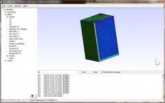
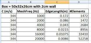
Easy enough to check. The box from post #102 will be used and its 50x32x26cm so approx 1/2 surface of your example. It has a 2cm wall so there is both interior and exterior. I used the formula from ABEC for the reqd edge length and used it to constrain GMSH max length. I know this will prevent ABEC remesh as it satisfies the edge length requirement. The results are in the table below. Even at 8Khz, with no symmetry, the #elements is in the range I could live with and I would use 1/2 symmetry to reduce it further.
Attachments
What is the purpose of simulating the interior? If you want the solution in the interior why do it at the same time as the exterior?
Using only 2 elements per wavelength will very likely produce plausible but inaccurate results. This is not good if you want to use the results to make reliable design decisions. If you used less the solution would be nonsense and obviously wrong which is in some ways more useful. If you used more the numerical solution would move towards the exact solution of the governing equations. The trick is knowing what resolution is required to be close enough to the exact solution for the results to be sufficiently reliable for your purposes. I mentioned earlier the usual approach to determine this.
Using only 2 elements per wavelength will very likely produce plausible but inaccurate results. This is not good if you want to use the results to make reliable design decisions. If you used less the solution would be nonsense and obviously wrong which is in some ways more useful. If you used more the numerical solution would move towards the exact solution of the governing equations. The trick is knowing what resolution is required to be close enough to the exact solution for the results to be sufficiently reliable for your purposes. I mentioned earlier the usual approach to determine this.
What is the purpose of simulating the interior? If you want the solution in the interior why do it at the same time as the exterior?
I sim with a driver model that uses the 2 sided diaphragm. The interior design effects the compliance and damping seen by the rear of the diaphragm. Mostly required for woofers [eg. sealed, BR, BPn, TH, etc] but it can be applied to others as well because every driver membrane has a coupled front and rear side.
Using only 2 elements per wavelength will very likely produce plausible but inaccurate results. This is not good if you want to use the results to make reliable design decisions. If you used less the solution would be nonsense and obviously wrong which is in some ways more useful. If you used more the numerical solution would move towards the exact solution of the governing equations. The trick is knowing what resolution is required to be close enough to the exact solution for the results to be sufficiently reliable for your purposes. I mentioned earlier the usual approach to determine this.
I have no problem with varying the mesh density to check for consistent or improving solutions. I just need to check the model size to be " reasonable" before I start sims.
It would be interesting to know if it produces more accurate/useful results compared with the simple lumped models used in most speaker design software. My expectation would be probably not at low frequencies but it would be better to know. At higher frequencies it would allow things like the influence of the driver frame and body on the rear of the cone to be examined.I sim with a driver model that uses the 2 sided diaphragm. The interior design effects the compliance and damping seen by the rear of the diaphragm. Mostly required for woofers [eg. sealed, BR, BPn, TH, etc] but it can be applied to others as well because every driver membrane has a coupled front and rear side.
It would be interesting to know if it produces more accurate/useful results compared with the simple lumped models used in most speaker design software.
Good question. May be you could do such a comparison? Would appreciate that.
I am neither a Windows or ABEC user but do intend to give ABEC a go at some point. It was going to be this weekend but I have got tied up doing other things. When I do give it a go the testing will be brief because the inability to file makes a comparison with the software I use difficult. I doubt it will extend to the types of simulations Don describes.Good question. May be you could do such a comparison? Would appreciate that.
On the other hand, I am performing 3D simulations of speakers using different software and a few weeks ago added to my to-do list coupling the 3D acoustic field within the cabinet to the simulation of the cabinet motion. In my current simulations the acoustic radiation from the front of the cone is removed in order to study the lower level radiation from the cabinet. I had not intended to include the motion of the cone/suspension/coil assembly but the additional effort required to do it is likely fairly small. However, it would likely be only for interest sake rather helping design my DIY speakers which means it would likely get lowish priority.
Also, I ran some benchmarks this week which were less than scientific, but here goes:
My laptop is a Ryzen 2500U with 16gb of ram. The core clock is 2ghz. One "neat" thing about the Ryzens is that they're so darn efficient, they can 'burst' up to 3.6ghz and they'll throttle back down if things get too hot. When I first started doing ABEC I had an Intel Core i5 laptop and about a third of the time it would get too hot and just crash doing sims. Real fun when a sim has been running for four hours. My Ryzen doesn't have this issue, the laptop doesn't even get particularly hot. Admittedly, older HP laptops had real thermal issues. (I should know, I used to work there and most of us dreaded the older laptops.)
I ran a sim on the Ryzen with forty frequencies from 1000 to 20khz and it took four hours.
I re-ran the same sim on my home theater PC, with 16 frequencies from 1khz to 16khz and it took four hours. My HTPC is an AMD A8 7400K, with four cores running from 3.1 to 3.8ghz.
So, clearly, the Ryzen stomps the A8. This should be no surprise. But the good news is that ABEC seems to run fine on older hardware, as long as you have a decent amount of RAM. My HTPC has sixteen gigs. Which is overkill for a HTPC, but I put it together back when ram was cheap.
On Sunday I managed to get my home lab working again, for the first time in about a year.
This gave me a chance to evaluate ABEC on a real beast of a system:
1 ) two sockes, sixteen cores
2) 32GB of RAM
The results of the test seem to indicate that RAM is probably the biggest bottleneck with ABEC.
While doing the test, I noticed that the simulation came *close* to finishing, in about fifteen minutes, and then it just hit a wall and didn't finish for about four hours.
While watching the system performance, I could see that the system ran out of RAM at about the fifteen minute mark.
So I think this is what's happening:
1) ABEC gives a fraction of the sim to each core
2) each fraction of the sim requires RAM
Due to this, when you have a lot of cores, you run out of RAM quickly. In my case, I have sixteen cores and 32gb of ram, so each 'slice' is only getting 2gb of ram. If I turned on hyperthreading, it would be half of that.
So that might explain why some people are doing sims with two or four procs, with no issue, while my sims are going off into la-la land for hours at a time.
I've noticed very little disk activity during the ABEC sims. So it looks like it's (mostly) running in RAM.
Based on all of this, I have a hunch that there's a couple of options for high performance with ABEC:
1) The cost no object option : basically buy as many CPUs and RAM as you can afford.
2) For an "affordable" ABEC system, it might be good to have a modest number of CPUs with very high clock speeds and a LOT of ram. IE, if we assume that each 'slice' of the processing is parked on one CPU, it probably makes more sense to have eight CPUs running at 4ghz with 32gb of ram total, instead of SIXTEEN CPUs running at 2ghz with 32gb of ram. The reason that fewer CPUs *might* be better is because ABEC seems to 'hit a wall' when it reaches the memory limit on the system. And after it 'hits that wall' it just slows down dramatically. I'd speculate that it probably tries to do the sim in memory, and when that fails, it probably copies the entire thing to disk. That copy will gobble up a lot of time, and the processing will be extremely slow on disk, when compared to RAM.
I'm speculating that something around 4-8gb per core is the 'sweet spot.' That means that I need to bump my rig up from 32gb of ram to 64-128gb. But my system only runs at 2ghz; if I had a new Ryzen or i7, I could probably get away with half as many cores and drop the ram requirements down to 32-64Gb, since modern processors are so much faster.
I think I have said this before but just to be sure; ALWAYS use a number of frequencies which is a multiple of your available number of threads.
ABEC does not chop the model over several threads but uses one thread per frequency.
This is why the first 90percent is real fast and then the last 10 percent is real slow.
So; 12 threads: 12 or 24 etc. freqs
Cheers
Kees
ABEC does not chop the model over several threads but uses one thread per frequency.
This is why the first 90percent is real fast and then the last 10 percent is real slow.
So; 12 threads: 12 or 24 etc. freqs
Cheers
Kees
Hi everyone,
brand new ABEC user here, trying to simulate an elliptical OS style waveguide. I am using SolidWorks for CAD, gmesh for meshing.
I am having the same problem I've seen several others here have had. A jagged looking sound field near the waveguide boundaries.

I read that this is usually because of the mesh. To me it looks alright to at least for lower frequencies?

I tried refining it, especially the throat section where there is a radius, but it made no difference except that the simulation time increased from a few minutes to 1.5 hours, so a bit much for initial simulations with purpose of learning.
I also think that the polar behavior looks strange at higher frequencies with large off-axis spikes 150-180 degrees at 6kHz, and I don't understand why the sound level inside the horn is so low compared to the outside of the interface...

Any ideas? I think there is something fundamentally wrong in my model, but don't know where to start.
brand new ABEC user here, trying to simulate an elliptical OS style waveguide. I am using SolidWorks for CAD, gmesh for meshing.
I am having the same problem I've seen several others here have had. A jagged looking sound field near the waveguide boundaries.
I read that this is usually because of the mesh. To me it looks alright to at least for lower frequencies?
I tried refining it, especially the throat section where there is a radius, but it made no difference except that the simulation time increased from a few minutes to 1.5 hours, so a bit much for initial simulations with purpose of learning.
I also think that the polar behavior looks strange at higher frequencies with large off-axis spikes 150-180 degrees at 6kHz, and I don't understand why the sound level inside the horn is so low compared to the outside of the interface...
Any ideas? I think there is something fundamentally wrong in my model, but don't know where to start.
Attachments

Hi Frederik,
There might be not enough information rearding your simulation to answer all your questions, but I give it a try anyway...
- Jagged sound field near the WG boundaries: This happens - you can stay away from the boundaries with the sound field, you can refine the mesh of the WG and the mesh size of the field, at the cost of calculation time of course.
- There are some very good contributions in this thread on mesh size and calculation time by DonVK and others. They give a good indication on upper frequency limit of the simulation and calculation time....
This could be a property of the OS waveguide, i.e. a typical SPL-drop on axis due to the conical WG-walls (depending on size of the WG, distance of virtual microphone).
Other possibility for the irregularity might as well be the membrane/driver simulated at the WG throat (is this a flat, round membrane driven by acceleration, or did you try to simulate a compression driver?).
Another question on your sim:
Did you simulate using an infinite baffle, or did you simulate with a back-enclosure?
From my point of view, your simulation is not fundamentally wrong, may be you can give some more details on your simulation...
There might be not enough information rearding your simulation to answer all your questions, but I give it a try anyway...
- Jagged sound field near the WG boundaries: This happens - you can stay away from the boundaries with the sound field, you can refine the mesh of the WG and the mesh size of the field, at the cost of calculation time of course.
- There are some very good contributions in this thread on mesh size and calculation time by DonVK and others. They give a good indication on upper frequency limit of the simulation and calculation time....
I also think that the polar behavior looks strange at higher frequencies with large off-axis spikes 150-180 degrees at 6kHz,
This could be a property of the OS waveguide, i.e. a typical SPL-drop on axis due to the conical WG-walls (depending on size of the WG, distance of virtual microphone).
Other possibility for the irregularity might as well be the membrane/driver simulated at the WG throat (is this a flat, round membrane driven by acceleration, or did you try to simulate a compression driver?).
Did you check the range and sensitivity for both observation fields in your script?I don't understand why the sound level inside the horn is so low compared to the outside of the interface...
Another question on your sim:
Did you simulate using an infinite baffle, or did you simulate with a back-enclosure?
From my point of view, your simulation is not fundamentally wrong, may be you can give some more details on your simulation...
I am having the same problem I've seen several others here have had. A jagged looking sound field near the waveguide boundaries.
I read that this is usually because of the mesh. To me it looks alright to at least for lower frequencies?
I am not an ABEC user but I am familiar with BEM. If I am reading your plot correctly, which I may not be doing, the jagged effect seems to be due to a vertex of your field mesh crossing your BEM mesh. The boundary integral being evaluated by ABEC won't have a value for such vertices and so something sensible is unlikely to be plotted without ABEC performing a lot of checking.
All the vertices in the field mesh must be outside the BEM mesh. Field vertices very close to the BEM mesh can also sometimes lead to wonky looking values and are best avoided as well.
Note this problem is independent of the computationally intensive matrix solution first stage which will not need to be repeated if ABEC stores the solution. Simply perform the second evaluation stage with a corrected field mesh.
Hi Frederik,
Hi Gaga, I was hoping you might show up 😀
- Jagged sound field near the WG boundaries: This happens - you can stay away from the boundaries with the sound field, you can refine the mesh of the WG and the mesh size of the field, at the cost of calculation time of course.
You say:
1. stay away from the boundaries. How? Adjusting the angle of the observe fields? Isn't that like pretending it didn't happen? 😀
2. Refining the mesh size of the field: is this the mesh frequency? I currently use 20kHz
- There are some very good contributions in this thread on mesh size and calculation time by DonVK and others. They give a good indication on upper frequency limit of the simulation and calculation time....
Yes, I will read everything once more to see if I'm overlooking something. DonVK has allreay been helping me out in a dfferent thread. I switched to this one, thinking this was the more appropriate place to post ABEC questions.
My reasoning so far was that mesh size and mesh frequency would be good enough to describe frequencies with at least twice the wavelength, but the errors seem to be there no mater what frequency I look at.
This could be a property of the OS waveguide, i.e. a typical SPL-drop on axis due to the conical WG-walls (depending on size of the WG, distance of virtual microphone).
Other possibility for the irregularity might as well be the membrane/driver simulated at the WG throat (is this a flat, round membrane driven by acceleration, or did you try to simulate a compression driver?).
A good point. I might have skipped an important step I have used in many FEA softwares in the past, replicating a known structure and compare my results to others. I could try one of the waveguides you have posted and see if I get something that looks similar.
Yes, this is a flat round membrane driver by acceleration, here is the solver file:
Code:Control_Solver f1=1000 f2=10000 NumFrequencies=6 Abscissa=log Dim=3D MeshFrequency=20kHz Sym=yz // Mesh File Setup MeshFile_Properties MeshFileAlias="M2" Scale=1mm // Subdomain Setup SubDomain_Properties SubDomain=1 ElType=Exterior SubDomain_Properties SubDomain=2 ElType=Interior // Boundaries //1-3 enclosure // 4 = driver // 5 = interface //6,7,8 = horn Elements "Horn" SubDomain=2 MeshFileAlias="M2" 101 Mesh Include 6,7,8 Elements "Exterior" MeshFileAlias="M2" SubDomain=1 10 Mesh Include 1,2,3 //102 Mesh Include 5, 6, 7, 8 Elements "Interface" MeshFileAlias="M2" SubDomain=2, 1 101 Mesh Include 5 SwapNormals Elements "Driver" MeshFileAlias="M2" SubDomain=2 101 Mesh Include 4 // Driving Setup Driving "Comp Driver" RefElements="Driver" DrvGroup=1001
Code:Did you check the range and sensitivity for both observation fields in your script?
Bingo! They were different, and since my itnerface is at the origo, the rearwards field is what I see inside the WG. Thanks!
Another question on your sim:
Did you simulate using an infinite baffle, or did you simulate with a back-enclosure?
No infinite baffle. I tried simulating a enclosure just around the back of the membrane. There is no outside wall on the WG itself. Is that necessary?
From my point of view, your simulation is not fundamentally wrong, may be you can give some more details on your simulation...
Ok good, then I will try to simulate some other waveguide contours and see how that works out.
I am not an ABEC user but I am familiar with BEM. If I am reading your plot correctly, which I may not be doing, the jagged effect seems to be due to a vertex of your field mesh crossing your BEM mesh. The boundary integral being evaluated by ABEC won't have a value for such vertices and so something sensible is unlikely to be plotted without ABEC performing a lot of checking.
All the vertices in the field mesh must be outside the BEM mesh. Field vertices very close to the BEM mesh can also sometimes lead to wonky looking values and are best avoided as well.
Note this problem is independent of the computationally intensive matrix solution first stage which will not need to be repeated if ABEC stores the solution. Simply perform the second evaluation stage with a corrected field mesh.
Thanks for the advice Andy. @Other ABEC users, is the field mesh controlled by the MeshFrequency parameter?
Anyway, it turns out that Gaga was right, there was probably not a fundamental error in my model after all; the polar plots I used were normalized and this gives that kind of shape for an OS profile of similar size when normalized to on axis. I also switched to an infinite baffle, which also seem to remove some of the funky looking results. It is also a more realistic condition, as I am trying to design an in-wall speaker.
Here is the same OS (aprox 10" size) contour again normalized:

Here is a 10" OS WG measured and normalized to on axis:

Same trend in both, even though wall angle and throat diameter is a bit different. (mine is 60 degree and 0.75" throat)
Here is the countour not normalized:

So with some renewed faith in my model I started tweaking the design and it quickly got to this:

A good start I think. I am not sure I will try to model the CD. I might start off with just 3D printing the contour and see how much it deviates from the simulation after EQ on axis and take it from there.
I think also the work flow is pretty good. As long as I have not introduced new faces, but just changed the wall contour, all the surface numbers are the same, so no changes to the ABEC script is necessary, I can just replace the mesh file and hit solve.
Does anyone have code exampe for plotting several SPL curves like Gaga did here?
Really appreciate the input and previously published work in this thread.
Last edited:
Off-axis curves
Answering my own question in case it could be usefull to others:
In the Observe Spectra.txt I wrote the following:
And got this in VACS:

Answering my own question in case it could be usefull to others:
In the Observe Spectra.txt I wrote the following:
Code:
  Nodes  "Spectrum"
    Scale=1mm
    5001      1600      0    0   // Point on-axis
    5002      1545      0    -415   // 15 deg off-axis
    5003      1385      0    -800   // 30 deg off-axis
    5004      1131      0    -1131   // 45 deg off-axis
    5005      800       0    -1385   // 60 deg off-axis
    5006      415       0    -1545   // 75 degoff-axis
    5007      0         0    -1600   // 90 deg off-axis

BE_Spectrum
    PlotType=Curves
    AnalysisType=Pressure
    RefNodes="Spectrum"
    GraphHeader="Sound pressure"
    BodeType=LeveldB;   Range=50
    101   5001 ID=5001
    102   5002 ID=5002
    103   5003 ID=5003
    104   5004 ID=5004
    105   5005 ID=5005
    106   5006 ID=5006
    107   5007 ID=5007
And got this in VACS:
Last edited:
Thanks for the advice Andy. @Other ABEC users, is the field mesh controlled by the MeshFrequency parameter?
Good to see you got it working.
MeshFrequency checks the edge length of all facets to see if they are at least 1/2 lambda. ABEC will remesh (subdivide facets) if there is a violation. It is also used to create the observation field meshes. It's a good way to check if your external generated meshes are fine enough. Set the MeshFreq to a low value, select mesh only in ABEC, then look at the #elements in the Solve tab. Change the MeshFreq to what you really need, then select mesh only in ABEC, and check the #elements in the Solve tab. If it changed alot (>10%) your mesh is not fine enough and you should remesh again in gmsh.
Hi everyone,
I am having the same problem I've seen several others here have had. A jagged looking sound field near the waveguide boundaries.
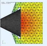
The jagged edge is from an observation facet intersecting another object and its not mesh aligned (as per @Andy19191, @Gaga). The facet cannot be resolved and its shown as a "whitespace". I just ignore them. However if you really want a clean edge, a) design your observation fields so they do not touch other objects or b) create the fields externally and mesh them so their facets are edge and vertex aligned to the waveguide/horn/cabinet. Increasing the MeshFreq will not prevent this.
A pic (field wires on) to show the field white space is a breached facet and the entire facet is whitespaced.
Attachments
Last edited:
FredrikC,
Thank you so much. I'd given up on ABEC for similar reasons. Looks like it's time to fire up my workstation and try out these solutions.
Thank you so much. I'd given up on ABEC for similar reasons. Looks like it's time to fire up my workstation and try out these solutions.
- Status
- Not open for further replies.
- Home
- Loudspeakers
- Multi-Way
- ABEC experts - help!