I was trying to envision it, but that probably just makes it more confusing.No, I think these two cases are hard to separate. A sound wave going down a rigid surface can't expand sideways. It is only when it hits the corner that its energy is allowed to expand (diffract) around the bend. This act of expanding signals a change of acoustic impedance which causes the reflection as well. This is just like a signal going down a transmission line: when it hits a change of impedance (open, short, or just different) a reflection is caused.
I see your point. Not being familiar with the wave equations, one question I have is what is the form of the impedance? That is, is it primarily resistive or reactive and if the latter, what is that reactive impedance? Certainly it's a function of frequency.To have a hard edge, where energy diffracts around the corner and then to replace it with a hard edge with flush absorption, appears to me to be the same case. Rather than continuing along a hard surface the wave is suddenly allowed to bend into an absorbing medium. To the extent that the absorber is a perfect absorber, the sound wave goes around the corner never to be seen (or heard from) again. No difference.
There is one additional factor, however. There will be two changes in the acoustic impedance with a damping medium. The first will be at the baffle/felt interface, the second will be at the edge of the felt. The key is in the difference in the two impedances. My suspicion is that due to the issue of angle of incidence, the difference is very small. Were it large, we should measure a more significant change in the on-axis response (when comparing with vs. without).
Dave
Last edited:
And how do you avoid the other textbooks?
I never see the term "diffracting off" of an object but rather diffracting around.
"Bending of light" is a common ussage, as shown by the dictionary definition that I quoted. Bending of light also occurs when transiting a medium of varying refractive index (as does bending of sound when going through a temperature gradient).
It may be "symantic"s but I think it is clearer to refer to diffraction as just the bending around an object and reflection as the re-radiation from the transition. That one typically is found with the other is understood.
David
I was trying to envision it, but that probably just makes it more confusing.
One of my college physics teachers had the coolest apparatus that was this long snake of wooden bar-bells tied together with springs. You could tweek one end of it and see the wave work slowly down to the other end. If the end was unattached a negative wave came back. If it was rigidly fastened the wave came back in phase. There was even an oil damper that absorbed the wave with no return and a second line of smaller size (different impedance). It was great for visualizing wave phenomona.
I'm not very good at the wave equation either. My understanding is that the acoustic impedance for a plane wave is a resistive 42 ohms per square cm. of the wave front. As a wavefront expands it is presumed to quickly become a plane wave (a sphere of large radius). I'm guessing that the "bending" of the wave around the edge means that it is, at least temporarily, not a plain wave and the impedance change stems from that. (I'm sure someone will correct me if my physics is in error.)I see your point. Not being familiar with the wave equations, one question I have is what is the form of the impedance? That is, is it primarily resistive or reactive and if the latter, what is that reactive impedance? Certainly it's a function of frequency.
There is one additional factor, however. There will be two changes in the acoustic impedance with a damping medium. The first will be at the baffle/felt interface, the second will be at the edge of the felt. The key is in the difference in the two impedances. My suspicion is that due to the issue of angle of incidence, the difference is very small. Were it large, we should measure a more significant change in the on-axis response (when comparing with vs. without).
Dave
My suspicion is similar. Also, if an absorber performs well its impedance should approach that of free space, shouldn't it?
David S.
Hi Speaker Dave,
My suspicion is similar. Also, if an absorber performs well its impedance should approach that of free space, shouldn't it?
So -6 dB SPL in the axial response compared to an infinite baffle
and no more of the so-called "baffle effect" ?
My suspicion is similar. Also, if an absorber performs well its impedance should approach that of free space, shouldn't it?
So -6 dB SPL in the axial response compared to an infinite baffle
and no more of the so-called "baffle effect" ?
I can't give an answer. Part of the problem in considering this is that thinking in terms of impedance in this way, how does it relate to the fact that we're considering an issue of 3-dimensional space?My suspicion is similar. Also, if an absorber performs well its impedance should approach that of free space, shouldn't it?
We also have to consider where the material is positioned in terms of performance. This relates to your question. What characteristic of felt, for example, do we consider good performance? Absorption only? Change in speed of propagation of the wave? Both? Would this be the same goal for both locations?
This goes back to the problem of understanding the mechanism of how felt is an aid in minimizing diffraction when placed on the front baffle. It's a different issue altogether if used, say, to form a waveguide. I doubt that the properties that make it useful on a baffle are the same properties that one would want in a waveguide.
Dave
That's how I understood it too. The wave bending around the sharp edge causes a drop in pressure to occur at the bend, launching a second out of phase wave from the diffraction point - but this wave propagates in all directions from the sharp edge, as shown by this diagram:In all the textbooks that I have read diffraction is that wavefront that is sent off from the edge, in this case. This would make the forward zone the direct plus diffraction field and the "shadow zone" the diffraction only. I think your distinction here between an edge reflection and an edge diffraction is symantic.
In all my writing and use of the term, the diffraction wave propagates in all directions not just into the shadow zone. And I believe that this is consistant with the physics literature on the sibject as well.
An externally hosted image should be here but it was not working when we last tested it.
In the case of a tweeter on a baffle where is the reflection though ? The wave that reaches the sharp edge of the baffle has been running along parallel to the plane of the baffle to get there.When a wave hits an object in space we refer to how the sound "diffracts" off of it. There is no distinction made between the sound that "reflects" off of it from the sound that diffracts off of it. It's all the same thing.
Unless the tweeter dome physically protrudes above the plane (which some do I guess) there is no chance for a reflection to occur, only diffraction.
I'm also not sure that I understand how diffraction and reflection can be one and the same - if a sound wave from afar impacts an infinite baffle and reflects off it, how is this equivalent to diffraction when an infinite baffle has no finite dimension for the sound to diffract around ? And yet an infinite plane will quite happily reflect a sound wave...
Also a reflection will reflect at the incident angle from the surface much like a beam of light in a mirror, yet diffraction will cause radiation in all directions from the sharp edge where diffraction is occurring as in the above diagram - diffraction becomes a secondary sound source while a reflection is simply a mirror image of the original source location. A sound wave reflection from a boundary is also in phase with the original at the point of reflection, while diffraction re-radiation is out of phase with the original at the point it occurs. Doesn't seem like the same phenomenon to me.
Last edited:
In all the textbooks that I have read diffraction is that wavefront that is sent off from the edge, in this case. This would make the forward zone the direct plus diffraction field and the "shadow zone" the diffraction only. I think your distinction here between an edge reflection and an edge diffraction is symantic.
In all my writing and use of the term, the diffraction wave propagates in all directions not just into the shadow zone. And I believe that this is consistant with the physics literature on the sibject as well.
When a wave hits an object in space we refer to how the sound "diffracts" off of it. There is no distinction made between the sound that "reflects" off of it from the sound that diffracts off of it. It's all the same thing. In the equations we use two terms to dscribe the field everywhere - the direct field and the diffraction field. In the shadow zone there is only the diffraction field, everywhere else the field is the sum of the direct field and the diffraction field.
That's understood and agreed.
That's how I understood it too. The wave bending around the sharp edge causes a drop in pressure to occur at the bend, launching a second out of phase wave from the diffraction point - but this wave propagates in all directions from the sharp edge, as shown by this diagram:
An externally hosted image should be here but it was not working when we last tested it.
In the case of a tweeter on a baffle where is the reflection though ? The wave that reaches the sharp edge of the baffle has been running along parallel to the plane of the baffle to get there.
The image above and explanation I don't get it. I think Diffraction requires an object in space. How do the baffle and it's edge fits in the Diffraction?
In the case of a tweeter on a baffle where is the reflection though ? The wave that reaches the sharp edge of the baffle has been running along parallel to the plane of the baffle to get there.
Unless the tweeter dome physically protrudes above the plane (which some do I guess) there is no chance for a reflection to occur, only diffraction.
I'm also not sure that I understand how diffraction and reflection can be one and the same - if a sound wave from afar impacts an infinite baffle and reflects off it, how is this equivalent to diffraction when an infinite baffle has no finite dimension for the sound to diffract around ? And yet an infinite plane will quite happily reflect a sound wave...
The reflection being discussed isn't due to sound hitting a surface from some angle above the surface, rather just the reflection of the wave that has been traveling across the surface.
As to diffraction and reflection being one and the same, we aren't really talking about conventional reflections, only those that come along with the act of sound diffracting around a discontinuity, the secondary re-radiation from an edge. Your infinite baffle won't have any edge reflections.
David S.
The image above and explanation I don't get it. I think Diffraction requires an object in space. How do the baffle and it's edge fits in the Diffraction?
The term diffraction applies here also. Diffraction means the bending (expanding) of the wave into the void after the boundary conditions change in any way. Sound can hit an obstacle in space (wall with an opening in it) or it can be traveling down a wall that ends.
David S.
Hi,
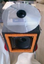
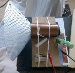
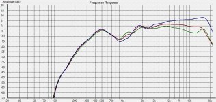
some kind of "lossy" or "defracting" WG i made two
years ago as an explorative prototype, which may
read more polite than "quick and dirty" ...
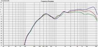
"A" is the driver in the stuffed tube without WG
"B" is with WG attached
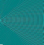
As far as i remember angles were
blue: on Axis
red : 20 degrees
green: 45 degrees (quite in line with the WG's "walls")
distance about 0.7m
A very different approach from felt of course ...
but absorption could also be added in several ways
outside the WG's walls.
Kind Regards
some kind of "lossy" or "defracting" WG i made two
years ago as an explorative prototype, which may
read more polite than "quick and dirty" ...
"A" is the driver in the stuffed tube without WG
"B" is with WG attached
As far as i remember angles were
blue: on Axis
red : 20 degrees
green: 45 degrees (quite in line with the WG's "walls")
distance about 0.7m
A very different approach from felt of course ...
but absorption could also be added in several ways
outside the WG's walls.
Kind Regards
Attachments
Last edited:
I think the main goal was to make a WG which has
low reflections back from the mouth even when
excited below its lower frequency limit.
A "smooth" crossover from wave guided to "free"
conditions if one likes ...
low reflections back from the mouth even when
excited below its lower frequency limit.
A "smooth" crossover from wave guided to "free"
conditions if one likes ...
It looks like your waveguide was essentially tranparent over most ot the frequency range. I'm not seeing much difference between with and without.
I suspect the same would happen with the foam walled waveguide. If the walls absorb or pass the sound it isn't a waveguide.
David S.
I suspect the same would happen with the foam walled waveguide. If the walls absorb or pass the sound it isn't a waveguide.
David S.
Hi David,
of course there is little effect below 3Khz, above there is a noticeable
modification of the directivity pattern.
The being effective is not just due to transparency, but also due to
length of the device compared to wavelength, like it is in a "true"
waveguide.
I am not sticking to terminology that much. Devices that modify
radiation patterns by diffraction or delay paths are also often
called "lens" or "diffusors" depending on what the functionality
seems to be mainly.
In ultrasonic devices e.g. arrangements of rods in the soundfield
are used to achieve focussing e.g. . Of course such arrangements
are usually optimized due to a specific frequency.
In this case especially the near off axis angles show less divergence
and i think if someone achieved a comparable effect using a different
approach, it would be regarded as kind of "noteworthy".
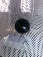
My internal name for that would have been "PerfGuide", not derived
from being "perfect" but from having perforated walls.
The arrangement can be modified in several ways, absorption of the
diffused radiation from the walls outer side is one of them.
But also "nested" spheres having variing transparency are possible,
to have a diffuse portion of radiation,which is angle dependent.
However i posted this as a present or inspiration to the community,
and whoever likes trying it as a base approach in modifying certain
driver's dispersion may do so ...
Btw. in that test speaker the tweeter was crossed in at about
2.3 Khz.
Kind Regards
of course there is little effect below 3Khz, above there is a noticeable
modification of the directivity pattern.
The being effective is not just due to transparency, but also due to
length of the device compared to wavelength, like it is in a "true"
waveguide.
... it isn't a waveguide.
David S.
I am not sticking to terminology that much. Devices that modify
radiation patterns by diffraction or delay paths are also often
called "lens" or "diffusors" depending on what the functionality
seems to be mainly.
In ultrasonic devices e.g. arrangements of rods in the soundfield
are used to achieve focussing e.g. . Of course such arrangements
are usually optimized due to a specific frequency.
In this case especially the near off axis angles show less divergence
and i think if someone achieved a comparable effect using a different
approach, it would be regarded as kind of "noteworthy".
My internal name for that would have been "PerfGuide", not derived
from being "perfect" but from having perforated walls.
The arrangement can be modified in several ways, absorption of the
diffused radiation from the walls outer side is one of them.
But also "nested" spheres having variing transparency are possible,
to have a diffuse portion of radiation,which is angle dependent.
However i posted this as a present or inspiration to the community,
and whoever likes trying it as a base approach in modifying certain
driver's dispersion may do so ...
Btw. in that test speaker the tweeter was crossed in at about
2.3 Khz.
Kind Regards
Last edited:
____
Btw. in that test speaker the tweeter was crossed in at about
2.3 Khz ... and that TB W69-1042J subwoofer produces
at least unattended quality in midrange for those willing to equalize.
Btw. in that test speaker the tweeter was crossed in at about
2.3 Khz ... and that TB W69-1042J subwoofer produces
at least unattended quality in midrange for those willing to equalize.
The BBC made a monitor once with the tweeters mounted on a perforated plate in front of the woofer. The perforation was sized so that it was fairly opaque for the tweeter's range but transparent to bass.
I'm picturing a waveguide with variable hole density. Might be another cure for midrange narrowing. Have you tried tape over the holes near the apex? Should be an easy way to experimentally vary the transparency along the length.
David S.
I'm picturing a waveguide with variable hole density. Might be another cure for midrange narrowing. Have you tried tape over the holes near the apex? Should be an easy way to experimentally vary the transparency along the length.
David S.
Wouldn't it be possible to make a waveguide out of foam completely? Ideally maybe varying the foam density from inner to outer layers?
Yes, Genelec has done it with the 8260A in the MDC coaxial driver:
Genelec Oy - Genelec 8260A
The foam is also functioning as mid cone and suspension.
From what I see, the foam is used on top of a more rigid material as driver, as waveguide and allows for no discontinuities. It does not appear to be used for damping anything from the tweeter, its function is as a waveguide in that respect. The same shape for a pure hard material would likely produce the same response. Their need was a material for the coax mid.Yes, Genelec has done it with the 8260A in the MDC coaxial driver:
Genelec Oy - Genelec 8260A
The foam is also functioning as mid cone and suspension.
Excellent system response, no doubt, but I do doubt that there are significant damping properties used for the tweeter response. Their description:
A proprietary midrange diaphragm technology - sandwich structure combining a rigid cone and elastic, lossy materials including the suspension itself.
It's not made exclusively nor even primarily of foam.
Dave
The term diffraction applies here also. Diffraction means the bending (expanding) of the wave into the void after the boundary conditions change in any way. Sound can hit an obstacle in space (wall with an opening in it) or it can be traveling down a wall that ends.
David S.
Dave,
Please correct me if I am wrong. For the diffraction to occur around the flat baffle, a tweeter must have dispersion over 180 deg on vertical axis or tweeter recessed deep inside the baffle which looks like a wave guide.
Maybe I'm wrong, but I don't feel "reflection" is the right word for this. In my mind diffraction and reflection are two different things with quite different properties.The reflection being discussed isn't due to sound hitting a surface from some angle above the surface, rather just the reflection of the wave that has been traveling across the surface.
Again, I'm uncomfortable with the use of the word reflection in this context, or the idea that there are two different kinds of reflection that are somehow different. Perhaps a terminology issue.As to diffraction and reflection being one and the same, we aren't really talking about conventional reflections, only those that come along with the act of sound diffracting around a discontinuity, the secondary re-radiation from an edge. Your infinite baffle won't have any edge reflections.
When a wave impacts a smooth surface from above it will reflect at the angle of incidence, just like light on a mirror. This is the mechanism which allows for the "image" theory of room reflection modelling where you have stacked rooms in all directions whose virtual speaker locations represent the incident reflections from the boundaries.
On the other hand diffraction off the side of a shoebox shaped cabinet is radiating roughly equally in a full 270 radius from the point of diffraction - its an omnidirectional radiation source whose beam-width is constrained only by the physical boundaries of the cabinet. (The cabinet "consumes" 90 degrees of the solid angle, effectively making a 270 degree "waveguide" for the re-radiated signal)
I fail to see how this could be called "reflection" in any sense of the word. Diffraction and reflection can exist independently of each other, although in many real world situations both will be present.
Other interesting facts with diffraction - the angle through which the wave bends controls the amplitude of the diffraction signature. A flat open baffle has a much stronger baffle diffraction signature than the same size baffle being the front of a shoebox shaped cabinet.
In the open baffle case the wave is bending a full 180 degrees around the edge of the baffle at once, while in the shoebox case its only bending 90 degrees, and by the time the wave gets to the back to complete the other 90 degrees it doesn't matter anymore, as discussed earlier in the thread.
Measurements I've taken on (wing-less) open baffles show dramatically worse ripples in the baffle step response even if the rear radiation of the driver is absorbed or contained to avoid interference...simply due to the greater bending angle at the edge of the panel.
One other thing that occurs to me, we generally think about diffraction where the baffle bends away to increase the sold angle the wavefront is bound by - like the edge of the front of a box, in this case the diffraction is out of phase because the expansion results in a pressure drop.
But what happens when the cabinet bends the other way causing the solid angle to be reduced ? Do we see an equal amount of diffraction (for a given bending angle) but with an in-phase diffraction signature due to a pressure increase ? Imagine a flat 180 degree baffle with a driver in the middle surrounded by a 45 degree forwards taper that looks like a very wide shallow waveguide, but with a sharp transition from flat to 45 degrees.
Are we going to see in-phase diffraction from that forwards bending transition ? I think so.
This has some relevance to the test box that dlr was measuring which has a stepped baffle, or any system with a separate tweeter pod on the top that is set back. From what I can see, a stepped baffle is going to have 3 effects happening at once.
1) A direct reflection from the tweeter off the horizontal surface of the stepped baffle. Depending on how wide that horizontal surface is and where the tweeter is located the range of incident angles mean that the reflection will be at quite a steep vertical angle and probably (?) won't be of significance within the listening window of the speaker. (For example it might only reflect at 60-70 degrees or more above the vertical axis where it will hit the ceiling and bounce back to the floor well before the listener)
2) Diffraction at the "corner" below the tweeter where the tweeter baffle switches from vertical to horizontal. Because this is a reduction in solid angle I suggest this would be in-phase re-radiation.
3) Diffraction at the edge where the horizontal section joins the vertical part of the woofer baffle. Because the wave is expanding again this should be out-of-phase re-radiation, and it will be being fed energy both directly from the tweeter at an angle, as well as from the previous diffraction in point 2.
The combined response of the three together (mostly the last two) is sure likely to make a mess of the response unless the driver has good directivity control and/or the edges are well damped as per dlr's tests...in other words a square edged stepped baffle with a wide dispersion driver and no felt damping is going to be a real nightmare...
Making the step a 45 degree chamfer would reduce the diffraction at both points 2 and 3, by reducing the angle the wave bends each time but certainly won't eliminate it. Making it a gradual S curve might help further but it would have to be fairly (unrealistically?) large to reduce diffraction at the tweeters low frequency end.
Last edited:
I don't have any problem with calling it a reflection. I've also hear people use the term "re-radiation" to describe the energy coming off the edge. I think that works too. I believe most of the diffraction modeling programs set up a perimeter line of secondary sources to model the edge re-radiation.
As justification, if you consider an electrical transmission line you can have a short circuit some distance down the line and see an in-phase return wave. (This would be no different than a hard cap termination on the end of an acoutical pipe.) If you change it to open circuit you will then see an out-of-phase reflection but you would certainly still consider it a reflection. The out-of-phase return wave from the edge discontinuity should equally be considered a "reflection", even though no hard surface caused it.
As to the forward angled baffle giving forward diffraction, that doesn't follow my understanding of diffraction. Sound moving along a baffle can expand forward but it can't expand backwards. The baffle is in the way. If the baffle ends then the wave has the opportunity to begin expanding backwards. It bends to move into the void. That is my understanding of diffraction.
By the way, we haven't discussed the frequency dependent nature of diffraction. Low frequencies will bend around the edge more readily than high frequencies. If a signal has run many wavelengths down the surface of the baffle then it is less able to bend around the corner. This explains the frequency dependent directivity of a driver on a box. It also explains why the directivity rises in an exponential horn: High frequency directivity is formed earlier in the throat where angles are steeper. For lower frequencies the directivity isn't fixed until further down the horn where the wall angles are wider.
David S.
- Status
- Not open for further replies.
- Home
- Loudspeakers
- Multi-Way
- Felt or foam walled waveguide?