
I agree!I like these threads which explore out-of-the-box ideas.
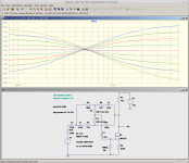
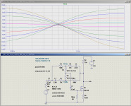
And in that spirit, here's an LTSpice simulation of the tone control circuit Galu posted back in post #58.
I've replaced the valve circuitry with an op-amp for convenience in simulation. The results tell you what the tone control circuit would do, as the tone knob was turned in small steps, in an ideal world, with an almost mathematically perfect amplifier (which has almost infinite voltage gain, and various other perfect attributes.)
As Snaarman said, it is sort of a treble control, though the simulation shows it works over most of the frequency range of a guitar. I would tend to call it a "tilt" tone control, which has the effect of tilting the frequency response one way or the other as the knob is turned; either bass-heavy and treble-shy, or the other way around.
The downside of a "tilt" tone control is that it is quite useless if you want to manipulate only one end of the frequency response, or if you want to boost booth bass and treble simultaneously.
I designed and built a different sort of tilt control for a guitar amp I built for a friend about a year ago. In testing, I found I liked it much more than I'd expected to. It was excellent for quickly adjusting the overall timbre of the guitar sound.
The friend I gifted that amp to has a knack for dialling in the worst possible tone from any guitar amp, and then staying resolutely with it. For him, the one-knob tilt control was a good thing: he could not find a horrible sound to dial in!

Back to Galu's circuit, the attached image shows only the amplitude response for simplicity. But LTSpice also shows the phase response. Looking at this, I can see why circuits like this are no longer used. The tone control circuit by itself produces phase shifts ranging from +50 degrees to -80 degrees depending on frequency and the position of the tone control knob.
Combined with the unavoidable additional phase shifts in the original valve amplifier, this is enough phase shift to make it quite likely that the amplifier will misbehave at some frequencies. Chances are the amp will be prone to oscillate at some frequencies, to howl or growl or chug or motorboat, as the tone control knob is turned through its range.
It is possible that another imperfection of the real valve amp - it's limited voltage gain - kept the original circuit from howling its head off. (It is also possible that it did indeed howl its head off, and that's why such tone controls fell out of favour.)
-Gnobuddy
Attachments
I end up in a smaller box every time I move to a different city. But they are all larger than the final box (or urn) will be!How come every time I think out of the box, I end up in an even worse box?
A hundred years ago, in the city where I live now, you could show up and state your intention to farm, and the authorities would give you 120 acres of land at no cost. Now a small apartment here costs half a million dollars, and a free-standing house on its own tiny scrap of land costs three times that much. Canada is a young country, and it is shocking how rapidly this part of it has gone from vast untamed forest to stratospherically priced gigantic asphalt lake.
-Gnobuddy
Thanks for taking the time to simulate the circuit and to explain its action as a 'tilt' control.. . . here's an LTSpice simulation of the tone control circuit Galu posted back in post #58.
The arrangement looked unconventional to me, so I avoided incorporating it into my build. Since you mention the possibility of oscillation, I am now glad of my decision!
P.S. My sympathy regarding your rising costs of city living. My humble 'but and ben' sits in a wee village which enjoys panoramic views over open countryside.
It's not exactly 'Brigadoon', but I do feel blessed!
YouTube
How come every time I think out of the box, I end up in an even worse box?
My advice to Schroedinger's cat: Think outside of the box...
That sounds lovely! I dream of getting away from "the great concrete", but that's where the jobs are.My humble 'but and ben' sits in a wee village which enjoys panoramic views over open countryside.
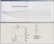
I'm attaching a simulation of the one-knob (tilt) tone control I mentioned earlier. This is an active tone control, and I used a JFET in the final build. The attached LTSpice simulation shows a MOSFET, however, and this works equally well.
This particular MOSFET will also handle several hundred volts, so it can easily be used in the middle of valve circuitry if so desired.
As with any active tone control circuit, it must never be driven into clipping. The trick is to put some sort of fixed two-resistor attenuator ahead of it, arranged so that the preceding stage reaches full clip (and full output) without the tone control itself being driven hard enough to clip at all.
As the curves show, this tone control has a flat response at the centre setting (it doesn't change the existing tone of the amp), and progressive, smooth, symmetrical curves as the knob is turned off-centre. It's great for making quick and easy adjustments to the overall tonal balance.
(But that's all it can do - you can't dial in bass boost alone, or mid scoop, or both bass and treble boost, and so on.)
Incidentally, this circuit has no insertion loss at the centre frequency, i.e., it has unity gain there. That makes it a good choice for use in an amp that doesn't have a lot of extra voltage gain to throw away - as long as you're okay with the limitations of a one-knob control.
-Gnobuddy
Attachments
Ideally, but I have high expectations from a tone control. I wanted this one to have a flat frequency response with the knob centred, and symmetrical curves around that point. I used it in a solid-state preamp, where it was easy to achieve such a low Zout."Source Z<1k"
It needs to be driven by a tube or FET 'follower' then?
It's not so easy in a valve preamp. How does that affect performance? The attached image shows what happens if the source impedance is 10k. The curves now droop by a decibel or so at the right end of the graph. Not quite symmetrical any more. But a decibel of droop is a very slight thing, probably inaudible with guitar as the source signal.
In other words, even with the droop, this tone control still produces far smoother and more symmetrical curves than you can get under any circumstances from crude passive "tone stacks" like the one that was invented for the Williamson amplifier, but which became known to guitarists from their use in Fender amps fifty or sixty years ago.
What if Zout is even higher? Typical Zout for a half-12AX7 with a 100k anode resistor is around 40 kilo ohms. With that high a source impedance, the droop increases to about 5 decibels across the entire width of the graph.
This is still easily compensated for by simply turning the knob to tilt the response the other way. But now the amount of boost and cut are not equal on the treble side, which isn't what I wanted (though the circuit is still much better behaved than the FMV "tone stack".)
-Gnobuddy
Attachments
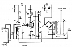
Progress report on the "one valve guitar amp" project: I can tell (from previous posts) I am treading a well worn path but this is where I ended up:
1: You can't quite make a one valve amp with an ECL82. You need more gain. If you want a conventional tone stack as well, you really do need more gain.
I'm limited by my 10w power transformer so I can't add a second valve, and anyway that would be two valves. Mostly it is the extra heater current.
So, in the spirit of engineering compromise I fitted a FET front end. Hey, rules are made to be broken, and anyway you can see the valve loud and proud. The FET is hidden where no one can see it
The FET provides gain and a moderate output impedance. This also allows a Fender blackface tonestack to go in before the volume control. Now a guitar pickup can push the amp properly.
2: I was able to reduce the triode anode resistor. I had pushed it to 180K but I felt that is just a tad too high, so now its 120K. This seems to clean up the amp at low levels.
3: I played with 2K on the screen grid feed (unbypassed) but the results seemed a bit harsh - so I went back to 200 ohms.
4: I have added a three position switch in the feedback loop. Position one is clean lower gain with quite a bit of feedback. Position two is Marshall mode - more gain with lower feedback using diode bending to simulate early breakup, finally in position three it can be Vox mode with no feedback. All three positions have some merit, though I find the "Vox" position a bit harsh. Pentode clipping seems to happen first at the positive excursion of the waveform. Increasing the bias current raises the clipping point, but I don't have much spare current I can give it.
5: I'm using the pentode cathode as a power supply (at 19 or 20v) for the FET front end. That seems to work just fine, with extra decoupling. In fact I put a LED in the feed so it slowly lights up as the amp comes to life. Cool touch
I'm testing it with a Fender 8 inch speaker and it sounds OK. However I also tried it with my 12 inch Greenback and it sounds just excellent (and a lot louder).
When I have settled on my values I will start a new thread and put the schematic up.
Pete
Last edited:

Congratulations on your new amp!
I believe you've found the very foundation on which most of human society is built - always hide the vital - but awkwardly inconvenient - details, and pretend they don't exist!
Tuning the values of the screen resistor and screen bypass cap can give you some compression / sag / bloom of your choice.
If we're going to have any innovation in DIY valve guitar amps before they breathe their last, it's probably going to come from people like you, who know how to design circuits, are willing to try something new, and haven't been blinkered by too much familiarity with the way Leo (Fender) or Jim (Marshall) did it sixty or seventy years ago. So thank you for sharing your ideas and experiments with us. I'm rooting for all of your ideas to succeed!
-Gnobuddy
As Mark Knopfler sang, "That's the way you do it!"The FET is hidden where no one can see it
I believe you've found the very foundation on which most of human society is built - always hide the vital - but awkwardly inconvenient - details, and pretend they don't exist!
You could use a bypass capacitor from screen grid to ground to change the overload characteristic. The harsh corners of the screen grid voltage waveform will disappear, along with the harsh overdrive, and you get sliding bias: when the pentode is overdriven, screen grid current goes up, and once the charge in the screen grid bypass cap is used up, screen voltage will drop.I played with 2K on the screen grid feed (unbypassed) but the results seemed a bit harsh - so I went back to 200 ohms.
Tuning the values of the screen resistor and screen bypass cap can give you some compression / sag / bloom of your choice.
I have that same reaction to classic VOX amps, too. What some hear as "chimey", I hear as unpleasantly gritty. One man's meat is another man's poison, as they used to say.I find the "Vox" position a bit harsh.
I'm looking forward to it!When I have settled on my values I will start a new thread and put the schematic up.
Pete
If we're going to have any innovation in DIY valve guitar amps before they breathe their last, it's probably going to come from people like you, who know how to design circuits, are willing to try something new, and haven't been blinkered by too much familiarity with the way Leo (Fender) or Jim (Marshall) did it sixty or seventy years ago. So thank you for sharing your ideas and experiments with us. I'm rooting for all of your ideas to succeed!
-Gnobuddy
is that with your 3db of regeneration?1: You can't quite make a one valve amp with an ECL82. You need more gain. If you want a conventional tone stack as well, you really do need more gain.
...
But I suspect you are right: even if you can get enough gain, the moment you start dumping gain (via tone) you're in trouble.
Last edited:
Yes, even with positive feedback there is not enough gain. I don't think switching to the ECL86 would fix the problem either.
The FET front end provides enough gain to save the situation even without source bypass. Plus it does it with a lower output impedance, so it's a win win.
If the FET is unavoidable, then there are some other tricks up my sleeve. I will try those in the next few days.
At present I just solved most of the hum problem with a trick from the 1950s
Pete
OK, the latest schematic is this attachment, this has the FET input and a standard Fender tone stack. I measured AC and DC voltages and noted them last night.

and the hum reduction trick is detailed in this forum linked below.
To explain - check out my schematic. Notice the pentode output transformer (from an 1959 UK radio) is a bit weird. The primary is tapped and it almost looks like an Ultra Linear transformer with the screen grid tap.
But no, you actually connect the B+ HT to the tap and the end of the transformer becomes an over wind. Even weirder, you use that over wind to power the rest of the amp through R23.
It becomes a hum cancelling tap. You trade off a small amount of amp power output for a considerable drop in hum. You do need a special transformer, but this seems a common trick in 1950s radios. So if you check the eBay listing before you buy one and count the taps then there is a chance you can chose one that has this over wind.
Of course this may be a common trick, but it was new to me... It certainly makes the amp a lot quieter, not perfect but very good for a guitar amp. I also avoided spending money on a HT choke
Here's the tech discussion. Note, they point out the extra tap is not a choke its a hum balancing winding. You need to tweak the value of R23 to get best results. The original radio circuit using my transformer used 1.5K but that was with a different pentode.
Extra windings on output transformers. - UK Vintage Radio Repair and Restoration Discussion Forum
Pete
Last edited:
Fascinating! A glimpse at a time when extra iron and copper (and the labour to wind the copper) was less costly than big electrolytic capacitors!the hum reduction trick is detailed in this forum linked below.
I've only made tiddly (very low power) SE amps, so I probably haven't had major power supply ripple issues to deal with. I also tend to use surplus photo-flash electrolytic capacitors in the power supply. The ones I have are 270 uF, 330V.
I got my photo-flash caps from a California surplus store, which is now out of 270 uF, but still has 150 uF photo-flash caps quite cheap: 150 UF 330 V PHOTO-FLASH CAPACITOR - SPECIAL PRICE | All Electronics Corp.
The big electronics component suppliers have similar caps in stock, though not at the same ridiculously low prices: https://www.digikey.com/product-detail/en/rubycon/450VXH330MEFCSN30X40/1189-2038-ND/3565655
One of these big photo-flash caps does a pretty good job of reducing power supply ripple, which isn't too surprising considering the capacity is ten times what was available / affordable in Leo's day!
When one photo-flash cap doesn't quite do it, two with a 47 ohm resistor in between (CRC) will usually kill the hum quite dead. A 270 uF cap has a reactance of about 5 ohms at 120 Hz (ripple frequency in North America, which has 60 Hz mains). So an RC section with 47 ohms and 270 uF will attenuate 120 Hz ripple by about 20 dB. Combined with the already low ripple across the first 270 uF filter cap, this has always done the trick for me.
I should mention that using an enormous filter cap can put a heavy strain on rectifier diodes and transformer windings, because peak currents go up - but only if your power transformer is big, beefy, and has very little DC resistance in its windings.
The cheap 2:1 power isolation transformers (240V/120V stepdown, turned around and used backwards) I use have about 30 ohms DC resistance in the windings, so peak currents are limited to a value which the usual 1N4007 rectifier diode seems quite happy with.
I did have one of these transformers that got warm with anything bigger than a 47uF first filter cap. Adding a series 47 ohm resistor and then a 270 uF filter cap worked just fine, though.
And now comes the heretical part - DC heater power! The affordable mains isolation transformers I use for power don't have 6.3V AC windings. These days, that is a blessing in disguise: cheap, clean DC heater power from a switch-mode power supply is a thrift-shop shopping trip away. I've never found a 6.3V supply, but 12V supplies are common and easy to use with 12A*7s and push-pull output stages (wire the two output heaters in series, then apply 12V DC.)
You can also use a supply that puts out a bit over 6.3 volts DC, and drop the extra voltage in a series resistor. A thrift-store refugee Sony 8.4V DC power supply, with a suitably chosen power resistor in series, supplies 6.3 V DC for all the heaters in my little push-pull 6AK6 amp.
For little low-power amps, there is also an intriguing new option for the high-voltage supply: Amazon.com: DAOKI High Voltage DC-DC Boost Converter 45V-390V 110V/220V ZVS Capacitor Charging Single Output Boost Module: Home Audio & Theater
That DC/DC converter can presumably be powered off the same 12V DC brick that powers the heaters, which could make life very simple for some small valve amp builds. I haven't tried this yet, but plan to do so.
-Gnobuddy
- Status
- This old topic is closed. If you want to reopen this topic, contact a moderator using the "Report Post" button.
- Home
- Live Sound
- Instruments and Amps
- Newbie: Hi there and a ECL86 question