If you must flog a vacuum, use Transmitter Tubes.
Most transmitter tubes need lots of voltage. The voltage alone brings risk and insulation issues, but also means a high impedance OPT with it's issues and restrictions. I started down this road with push pull 813's but quickly found that they really want over 1000 volts to ROCK! The OPT wants to be in the 10,000 ohm range which isn't a common thing, but 500 watts per pair is possible. There is a DIY 1000 watt guitar amp out there that uses 4 X 813's. It has been mentioned here a few times, but I couldn't find it with a quick search.
I still have a single ended 30 WPC amp that runs 845's, but it's about to be challenged with a SE sweep tube amp. After cracking the 500 watt barrier with sweep tubes, I sold all my transmitting tubes.....including the 4-1000's.
Squeezing a couple hundred watts from a pair of 4D32 transmitting tubes can be done on 650 volts, and would definitely win in the killer looks department.
Attachments
Last edited:
Conflicting opposite goals. Pick one, or meet halfway, in which case none will be completely fullfilled.My goal is to design the output stage of a music instrument amp using a pair of KT-88s. Subject to the limitations listed, I wish to extract every Watt possible from these tubes. Every. Stinking. Watt.
I wish to eliminate or at least minimize crossover distortion, so Class B is out.
Real World designing practically always means some kind of compromise is accepted
Well, you can take measures about that.Although I'm a fan of Neil Young, blocking distortion is also a no-no.
We keep adding restrictions to "Every. Stinking. Watt."I wish a pair of tubes to have a lifetime measured in months (years if possible) and not hours, so super hot-rodded lab curiosities are out.
")
Any specific reason for that?I do not wish to have any solid-state devices beyond diodes in the signal path. Sorry, source-follower lovers. I do not object to them elsewhere in the design, for example, in a rectifier.
A "source-follower" can inject quite a few mA into KT88 grids, allowing higher power Class AB2.
A Cathode Follower can in principle do the same, but complicating design (and power supply) a lot ... and not offering that many mA.
That´s a sensible decision.Edited to add: I don't want to use any tubes that can't be found at your local music store. So, things like 12AX7, 6L6GC, El84 are fine. 300B, KT120, 6SN7GT, probably not.
Don´t complicate your life beyond necessaryAside from that, anything goes. I do expect to be hitting this output stage with some severely clipped signals from time to time, and to sometimes drive it into clipping regardless of what comes in the front door. So, any topology that fits the above is on the table, such as screen drive if that fits.
, screen drive is possible but requires far higher drive signal.Cool.I may be interested in winding my own transformers, so consider impedences as "free" and concepts like coupling transformers in play.
Just checking ... can you also design them?
Here's a summary of what I've considered so far:
Somewhat unusual definition but let´s see where it leadsI consider everything to the right of the left-hand side of the Ra curve to be available, as if the tube was some sort of big diode.
I thought Class B was off-limits.Given that, maximizing power with an acceptable tube life seems to be an exercise in drawing a class-B loadline that does not exceed an arbitrary plate-dissipation number.
A commendable goal.For that number, I have chosen 96 Watts, based on the fact that a couple of successful commercial designs have loadlines that are in the 94-97 Watt territory, namely the 200W Marshal Major and the Hiwatt DR201 and DR405 (about 200 W and between 300-400 W respectively). The Marshall and the DR201 use 2 pairs of KT-88s in push-pull, the DR405 3 pairs. I'm only using one pair, but I want to see if I can get more power than that from my pair by using clever design.
Now you have to achieve it
Nor need to have "somebody" tell you.If I want to refer to previous work, I should also mention the Fender PS 300 and PS 400, which used 2 and 3 pairs of 6550As, rated at 42 Watts plate dissipation, in Class AB2. Va(o) was 700 V, Vg2 was 350 V, and I don't know what the load line was because I don't know the impedance of the output transformer.
You set voltage and current limits in datasheet curves, then draw optimum load line, that sets desirable impedance.
"Straight from the mouth of the horse"
You will find that yourself.So, they may have been able to run at lower maximum instantaneous plate dissipation by getting more voltage swing and current swing via Class AB2 (or more power per pair at similar dissipation levels).
I figure worst case is a clipped input resembling a square wave at just the wrong signal level, which would give me a continuous plate dissipation of 48 W. The commercial amps survived that, the Marshall with about 60 V of sag at the center tap. I suspect the sag for the Hiwatts was minimal as both the output transformer and power transformer were huge.
IF supply voltages are *stiff* , in practice regulated, your Math will apply.Playing with loadlines, I find I maximize power up near maximum allowable B+ of 800 V, and output impedance at 6.7k Ohm. At the opposite end of the loadline, current swings up to about 430-440 mA at about 70 V. To get current up that high, I need Vg2 at least 350 V or so. Pout is a rather fabulous 158W, if my calculations are correct.
Anything that sags, anywhere, will steal from that.
That´s a problem.That led me to my first real obstacle. At that plate voltage and screen voltage, screen dissipation is unacceptably high, some 20 Watts or so with a clipped waveform.
Nothing mysterious: notice that plate current keeps increasing beyond 0V grid 1, only problem being they now take significant current.I began to look at Class AB2 operation for relief. I don't know much about AB2, but looking over the 6L6GC datasheets, I was led to believe that available plate current can be raised by either going to a higher screen voltage or by taking grid voltage positive, and that for a given available plate current, screen current will be about the same no matter which scheme is chosen.
If that is true, I can lower screen dissipation by keeping screen (and plate) current about the same, and trading off screen voltage for grid voltage (not at 1:1, of course).
Sort of: just lower screen into safe values, check datasheet how much positive voltage you need on G1, and whatever maximum current you get under these constraints, is what you have to work with.
Don´t wonder or estimate, just get the real hard numbers from datasheet curves.I started wondering how low I could go on the screen and how high I could go on the grid, and that led me to this circuit from the GEC KT-88 datasheet. It's a Class B circuit rated at 150 W with RL(a-a) at 6k Ohm "for speech only". 7.5k Ohm is recommended for "other purposes", and I estimate the circuit would produce maybe 120 W with that load.
Do not tweak other circuits, just design your own from curves available.Now, this is a Class B amp, but I'm more interested in what's going on inside the KT-88s. Under "Operating Conditions", it lists Vin(g-g)(rms) = 360 V. Just to verify this isn't a misprint, the text reads, "Both grids are driven into the positive region from a driver stage capable of providing 180+180V r.m.s., the current drawn by the control grids being limited by R18 and R19." R18 and R19 are listed as "22-100k Ohm 1W".
Do not tweak other circuits, just design your own from curves available. [2]Maybe I'm just new at this, but if I understand this right, that means each grid is getting hit with a positive 255 V at peak. I struggle to comprehend KT-88 operation under those conditions.
You describe a reasonable way.So, let me summarize what I hope to learn:
Is there any other topology or arrangement which would allow me to extract more power from these tubes without blowing them up? Meaning, other than a more or less conventional Class AB2 grid-driven stage with fixed bias, or other than some variant of the attached schematic?
Again: "Do not tweak other circuits, just design your own from curves available.".Is there any other way to lower screen dissipation at these power levels?
Can I modify the circuit in the attached schematic to run in Class AB2 instead of Class B? Or is there something that works even better?
Thanks for your advice and suggestions.
All your answers are in those datasheet curves.
I'm pretty sure this is going to lead to something different, or at least something that was abandoned that could have worked.Want a different "tone" be prepared to do something different.
And speced at 1250 V contact-to-contact, used in 1970s-era military field radios, among other things. Still available from Eby (didn't check to see what their minimum order was) and various military parts suppliers (minimum order $100 and I'm afraid to ask what the per-unit price is).It's the bases and sockets that are the problem...I found a box of NOS ceramic sockets in a military surplus store maybe 35 years ago.
Let me know what my options are (lowering B+ counts as one of them), and I can go study and make an informed decison about which one I prefer. It would be very convenient if big voltage transients always came rolling in on the side that was cut off. Switching during the nonconducting part of the cycle appeals to me, and that's something I would consider doing with silicon.Several methods to limit the peak voltages have been introduced, and I have tried most of them...Depending on what you are trying to accomplish, this still may be a valid choice.
I'm working my way through Kuehnel's Power Amps book, trying to see exactly what I'm getting into here.Reducing the B+ from 600 volts to 450 volts is a reduction of about 3/4...It's however, not that simple.
At this point, I'm under the impression that I'll more safely get to 110 watts in AB2 than I will in AB1, but I'm keeping an open mind.You can get 100 watts from a pair of KT88's by running them at 600 volts into a 5000 ohm load in AB1. You can also get 100 watts from a pair of KT88's on 450 volts into 3300 ohms in AB2.
If you look at post 18 in this thread, you'll see what I'm thinking of in the way of OPTs. Don't take the primary impedance too seriously. I picked that number to fit a case I had in a spreadsheet, and worked out everything else from that. I note that Wolpert's guide really doesn't address capacitance at all, but that his design examples all outperformed his calculated high end response when built and tested.An OPT is an exercise in tradeoffs and compromises.
For now, let's assume the speakers are plugged into the correct nominal output inpedance jack, and that they are the ones from the catalog that are most likely to do something bad to the amp.The peak voltage seen on the output tubes are MOST AFFECTED by the speakers, since their resonant peaks are all different.
Alas, I shall have to find some KT-88s priced not for the perfect sound, but for research.Here some experimentation is needed...
I saw several listings similar to this one, and wondered if it was a way to get from A to B. Ah well, back to the drawing board.The rectifier socket was specially designed for the HV rectifier tube (usually a 3A3), and will not fit the diameter of any useful audio output tube, and most would not take the heat.
AMPHENOL 77A-8T HIGH VOLTAGE 8 PIN OCTAL (K8A) RECTIFIER TUBE / VALVE SOCKET | eBay
I know how to measure a watt, and I have a curve of human perceived loudness vs. frequency. Beyond that, I'm wandering in the weeds.There is a difference between "loudest amp" and "most powerful amp"
I"m reminded of stringed instrument players (guitar, banjo, ukelele, etc.) in large acoustic bands who complained about not being heard, and then found ways to shift the timbre of their instrument up so that it would "cut through" the band's sound. Wasn't any louder, but you could hear it better.
But especially if I can't control what speakers it's plugged into, and I can't control what input signal come into the front end (which might already have a distortion characteristic from numerous stomp boxes and preamp stages), I don't know how to dial in loudness with the distortion characteristics of the output stage. If I can get smarter on that, I might be willing to make that trade. But until then, I'm still chasing watts.
I'm still at "see if there's a way to squeeze out a few more watts without blowing the thing up", and then seeing if the result is musically useful. When EL34s were first created, nobody expected a musician to drive them to 40% distortion, but musicians do that, and the result sounds pretty glorious.As with ANY project of this magnitude, it is wise to first figure out what your main objectives are.
So, here's the latest iteration of where I'm at, and you and the others here can correct any errors in my thinking.
1. I'm still trying to figure out where the loadline goes, based mostly on the limitation of the tube. Looking at the plate, one constraint is B+ at 800 V, and the other is Pa at 42 watts. Ia(max) is listed at 230 mA, but that is quiescent. I assume that I can safely go to 3x that, 690 mA instantaneous.
2. I assumed that at the worst case, the loadline could pass through 96 watts based on loadline information for existing commercial amps. I understand that if the controls are set "to the heart of the sun", and the master volume is set to just the wrong place, I will have a 50% duty squarewave sitting at that point and an average Pa of 48 watts. Somehow, that doesn't blow up a Hiwatt..or at least, maybe nobody plays a squarewave through one at just the exact wrong volume setting...
3. I played with different B+ voltages, setting the OPT impedance to let the worst-case instantaneous Pa get no higher than 96 watts. I assumed that there was some way in each case to get the upper left limit of the loadline to approach the tube diode line, either through raising screen voltage or driving the grid positive, or...magic. My spreadsheet then told me that power was maximized with B+ at 800 V, Zout at 6700 ohms, Ia(maximum) at 434 mA and Va(minimum) at 72 V (right on the diode line). Pout for that was 158 watts. Output power fell slowly but steadily as B+ was reduced, down to 600 V, Zout at 3750 ohms, Ia(max) at 543 mA, Va(min) at 91 V, and Pout at 138 watts.
4. There are several assumptions above, and I am now keenly aware that B+ of 800 V may be workable when building something to the RDH, but not something that gets slammed with a series of squarewaves that overdrive the output stage. Most specifically, there are high induced voltages from the speakers and OPT that may exceed the capabilities of even the best sockets, insulation, wiring, etc.
5. I looked at that 434 mA Ia for the one case, and found that I needed Vg2 to be at least 350 volts to allow that, and that at Va = 72 volts, Ig2 was about 99 mA and Pg2 17+ watts, even if the screens were turned off at plate crossover. Clearly, that won't do. So, I'm looking at trading off a lower Vg2 for Class AB2 operation, using the grid to boost plate amps where the screen would overheat at the job. That takes me to...
6. "Twin drive" or "crazy drive", or whatever you want to call it. The advantage is that the screens and grid get switched off during cutoff, so I only dissipate half as much power in each over time. Rather than just tie the grids and screens together with a current limiting resistor on the grids, I'd like to control the input to each of them separately as a function of the input signal, such that when the input driver is maxed out and clips, I have one distinct voltage at the screens and a different one (much lower!) at the grids. No, I don't know what any of those values are, and that may be the "needed experimentation" that Tubelab_com mentioned.
7. Everyone has been talking about much lower OPT impedance than my spreadsheet shows, and Kuehnel's book has some good reasons why that may be so. If so, that rotates my loadline clockwise, and I end up with even higher Ia requrements to get the "most" power. It may be that the design is limited by how much plate current I can flow at low plate voltage without blowing up the grids and screens.
8. As if this wasn't all complicated enough, I've been looking at Class G and Class H circuits as a means to "bend" the loadline around the region of highest plate dissipation. But even if that's successful, I think I still have the problem of high plate current at the top left end of the loadline, so the comments about the screen and grid above still hold. And as an aside, if I need a third KT-88 to switch the B+ from one rail to another, I don't consider that cheating on the "2 KT-88s" requirement. And yes, that's another chore I would consider using silicon to do.
9. I have had some ideas on how to cope with the induced voltage on the plates problem, but suspect that I'm just re-inventing the wheel and so will wait and see what wonderful voodoo Tubelab_com et al can lay on me. And I'm still crunching through the reading list that Thoglette gave me back in post 15, including about 40 pages per day of RDH review.
Truth! But if I was just copying a schematic, I'd already be sourcing parts.In ANY design, the probability of success goes down as the power or voltage level goes up.
And I wish you much success and joy with that project.My main issues are, I want a kilowatt of output power, it must be able to eat my guitar playing at full crank, and the biggie......I must be able to carry it up the basement stairs, and I'm 66 years old.
Squeezing a couple hundred watts from a pair of 4D32 transmitting tubes can be done on 650 volts, and would definitely win in the killer looks department.
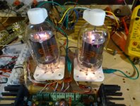
That looks good enough to reverse the trend of large stacks of fake amps. Just have one of those on the stage, point a camera at the output tubes, and show the video on a screen behind the guitar player!
Everything is "subject to the limitations listed". I'm just bounding the problem. If there were no limitation, I'd wire up a couple of transmitting tubes and be done with it. I want to find out what I can do 1) with a pair of KT-88s 2) that don't operation in Class B 3) that have no blocking distortion...Conflicting opposite goals. Pick one, or meet halfway, in which case none will be completely fullfilled.
The "no silicon in the signal path" constraint is probably the softest one, meaning that it's the one I'm most likely to give in on. But the reasoning is...Any specific reason for that?
I don't know what I'm going to end up buidling. At this point, I don't have a design. I'm just trying to understand what I can do with the tube wtihout blowing it up. As I flesh that out, I expect a concept of operation to emerge: I want the load line here, I want the grid to do this, I want the screen to do that. Once I have that, I can design circuitry to do those things. That might take me to a very tried and true topology, or it might take me someplace unusual.
However that takes shape, there will be some kind of driver, and that driver may be driven well into distortion. That will necessarily color the sound. If so, I'd prefer that be tube distortion. Now, there may be some way to do this with a transistor such that it never saturates, or if it does, the effect on the sound is barely audible. But since I don't know that up front, I'd prefer to keep that complication out of it unless absolutely necessary.
Well, I can follow a design guide like Wolpert's. If necessary, I can grab a much more technical reference and go from there, but for now, Wolpert seems adequate. I did a (very) rough design back up in post #18 just to see if my concepts were driving me to something absurd, and thankfully, it all came out much more "normal" than I feared.Just checking ... can you also design them?
I found that for the purposes of determining A) what the B+ was, B) what the maximum instantaneous Pa was, C) what the Ra(p-p) was, and D) what the output power was, you only need the Class B portion of the loadline. Once that's set, you can just decide how hot or cold you want to bias for Class AB, and draw in the Class A portion of the loadline.I thought Class B was off-limits.
Of course, all this assumes that you can get the top of your Class B loadline to go all the way to the diode line. Otherwise, you're back to more conventional techniques of setting all these values.
For clarity's sake, my goal is more power per pair. I have absolutely no illusions that I'm going to get 400 watts from a pair of KT-88s.A commendable goal.
Now you have to achieve it
Except that both those Fender amps operated in Class AB2, and there is no Class AB2 data for KT-88s.Nor need to have "somebody" tell you.
You set voltage and current limits in datasheet curves, then draw optimum load line, that sets desirable impedance.
I could maybe fudge a bit from the 6550 data curves, but it would still be a WAG.
Right. My spreadsheet did not account for any sag; at that point, I didn't know how much sag to expect.IF supply voltages are *stiff* , in practice regulated, your Math will apply.
Anything that sags, anywhere, will steal from that.
I am also aware that sag may be the reason some of those commercial amps might have been able to set the loadline where they did; ie. they'd have exceeded Pa had it not been for sag.
Here, the "checking the datasheet" thing may be a problem. Even the big GEC supplement for the KT-88 doesn't have that.Sort of: just lower screen into safe values, check datasheet how much positive voltage you need on G1, and whatever maximum current you get under these constraints, is what you have to work with.
This is where I might have to scrounge for expendably cheap KT-88s and start experimenting.
Just have one of those on the stage, point a camera at the output tubes, and show the video on a screen behind the guitar player!
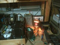
If that's the object, then pass on the 4D32's and go for the showpiece 833A. It was originally designed for AM radio transmitters and made to operate normally with the plate glowing red. Two of them in push pull can make 1000 to 2000 watts of audio power.
I was considering making a monster Single Ended stereo amp with these about 15 years ago and I paid a well known transformer winder some $$$$ to make me a test OPT. It wasn't quite good enough for HiFi, so I plugged my ADA MP-1 into the test amp and annoyed my neighbors with a 200 watt SE guitar amp that sounded like a Fender Champ on steroids.
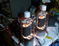
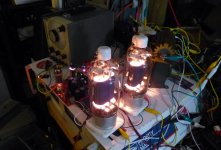
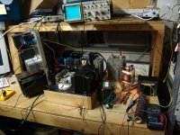
This thing was an exercise in UNSAFE practices with vise grips and hose clamps serving as a tube socket, 1500 volts at 300 mA passing through a Radio Shack clip lead, and powered by the power supply from a Motorola radio transmitter made for a police station. This thing took over my entire workbench, and existed for only one week. I had a Lexan "blast shield" between me and the amp whenever it was on (except for a few photos), mostly since touching anything on the bench could have been fatal. There was also a fire extinguisher at my feet during testing.
During the "testing" nothing blew up, but I did blow the 15 amp bench breaker twice by doing speaker to guitar feedback. The low frequency growls with the whammy bar were what dimmed the lights and blew the breaker.
I still have the parts from this test a long time ago. Will I ever make that "Uber Champ"? I don't know, right now the 4 watt tube amp I built is loud enough.
found ways to shift the timbre of their instrument up so that it would "cut through" the band's sound. Wasn't any louder, but you could hear it better.
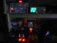
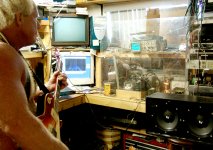
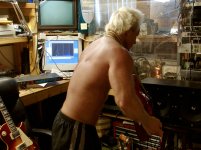
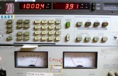
If you notice the CRT monitor in some of the pictures you will see a spectral plot of what's coming out of the amp. Each of the vertical lines represents a single tone, or musical note. Each is at a specific frequency in the human hearing range. Even though only one to six notes ate being played, each has harmonics and they all intermingle in this highly distorted amp chain.
If you want to be heard over all the other sounds in the band, you make a similar plot for each sound source in the band, then tweak the timbre of your "instrument" to occupy the empty spaces that are not being served by the other instruments. Ideally you would do this with much cleaner notes than these. These photos were taken with the ADA MP-1 set on a preset I called "Jimi" and it is already "cranked" in the preamp. Then it gets fed to the power stage which is dialed way beyond "11."
This is also why a distorted amp sounds louder than a clean one. There are many more tones present in the speaker, and therefore much more stimulation to the ears, that a "clean" amp with a few tones. The combination of these many tones is what gives a guitar amp its characteristic "tone" or "sound."
Attachments

If that's the object, then pass on the 4D32's and go for the showpiece 833A.
I think I prefer blue to red for aesthetic reasons, but I'll admit that 833A is intimidating, and in all the right ways.
I was going to just say, "Well, I think it has to be able to be driven into that region, so that should take care of apparent loudness from the extra harmonics", but then I realized that purposely limiting how far it can be overdriven might allow me to safely get a couple of more watts out of it.This is also why a distorted amp sounds louder than a clean one.
But, to my mind, that defeats the purpose of building a tube amp, unless you're specifically going for some variant of a "vintage" sound, so no. "Set the controls for the heart of the sun." (It's been a while since I've heard that.)
"Every. Stinking. Watt."
Any specific reason for that?
A "source-follower" can inject quite a few mA into KT88 grids, allowing higher power Class AB2.
A Cathode Follower can in principle do the same, but complicating design (and power supply) a lot ... and not offering that many mA.
....
Don´t complicate your life beyond necessary
... can you also design them [transformers]?

The one thing I don't have in my schematic archive is an amp with an IT driving both screens and grid 1. Now that'd allow you to drive the tubes to within an inch of their lives.
I've been thinking of exactly that.The one thing I don't have in my schematic archive is an amp with an IT driving both screens and grid 1.
That particular schematic is in the GEC Application data sheet for the KT88, issue 3. It's 9 Megabytes big, so can't be included here. There are several amplifier designs included with full descriptions and design explanations. This schematic is a 150 watt class B amp using the ICAS ratings (intermittent service, beyond the continuous ratings). I have seen similar schematics dating back to WWII often running a pair of 807's for 100 watts.
My experiments along these lines were over 20 years ago, and for guitar amp use. The value of the resistor on G1 is a tradeoff between power output, distortion, and sound quality. The resistor that made a reasonable sounding guitar amp made G1 glow every time you leaned on it. A larger resistor sounded ugly when the amp wasn't driven to clipping, probably due to excessive crossover distortion. It might be OK for announcing the horse race at the track, but sucks for guitar.
This was about the time I got the idea of sticking an audio output transformer into an old ham radio RF amp and discovered how much fun TV sweep tubes on 750 volts were.....really loud too. Note that the fire gods will have a party and dance all over your OPT when the load resistor blows open somewhere north of 150 watts.
See page 16:
http://www.mif.pg.gda.pl/homepages/frank/sheets/084/k/KT88_GEC.pdf
The goal is to meet or exceed both the power per pair and the reliability of previous commercial amps. I'm hunting for data on both.And here I am for using two pair of tubes, and rather than changing one pair out once a year you have two pair last for years.
For example, here's 312 W from 2 pairs of KT88s.
YouTube
here's 312 W from 2 pairs of KT88s.
That amp has 6 X 6550's. That's 104 watts from a pair. I have done that with some really cheap Chinese KT88's.....and they are still alive.
I bought about a case and a half (100 tubes per case) of some Chinese KT88's in the mid 1990's when they first started importing them here. A popular tube seller decided to quit carrying them after nearly half of those he sold came back, dead....or worse. I bought his remaining stock, cheap (about $5 each I think). I had been using Sovtek 6550WA's in my amp designs. They ROCKED, and I still have a few. The Chinese tubes blew up at 35 watts on 430 volts. This was the first time I ever saw a tube spark out so bad that it shattered. I graded out some good ones that didn't blow up and still have 5 good ones I think.
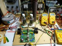
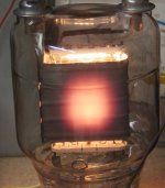
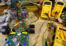
I popped a pair into a test amp. And cranked them up to 100 watts where they made 3.9% THD. Load impedance was 3300 ohms and the power supply was making 520 volts and 300 mA. That's 156 watts of DC power going into the plates, and 100 watts of audio coming out. That means 56 watts is burned in the two tubes, for 28 watts plate dissipation per tube.......well within spec!
Note that the camera I used in these pictures picks up infrared and shows it as a pinkish purple.
Attachments
I also have the schematic attached to the very first post in this thread.That particular schematic is in the GEC Application data sheet for the KT88, issue 3.
I don't understand how that amp is biased. Quiescent, I see 0V on the screens and grids, so it's all operating on the grid self bias? If it is in hard class B, I can understand why it doesn't make a good guitar amp.
Under load, it says the driver produces 180 + 180 vrms. 255 V peak on each screen? And at 255 V and a 22k grid stopper, I have positive grid current of 11 mA and grid voltage of +12 V.
11 mA makes the grids grow? Is my understanding of the circuit correct?
Ah, exactly right. I should have re-watched the video from the start, he shows the 6 output tubes. It's labeled a PS 300, but it was the PS 400 that had the 6 6550s (and supposedly 435 watts from 3 pair), and the PS 300 that supposedly extracted 300 W from 2 pair.That amp has 6 X 6550's.
So much for manufacturer's ratings.
The new, reconstituted Hiwatt company has reissued their 400W bass amp, but with 4 pairs of KT-88s instead of 3. They also claim 580 Watts from the new machine...145 W per pair if you can trust that.
Thanks for sharing your experimental data. One question:
To get 100 W from 520 V B+ and 3300 ohms load, I need Ea to swing all the way down to 113 V and Ia all the way up to 493 mA. Is that right?
Then not a bad idea to copy a commercial amp. Most likely they went through different iterations in design to achieve a level of reliability. So coming from a guy with tinnitus, where do you plan on cranking this thing? I had a cousin with a Twin Reverb and even with a heavy hitting drummer he could not get the output stage into clipping.The goal is to meet or exceed both the power per pair and the reliability of previous commercial amps. I'm hunting for data on both.
For example, here's 312 W from 2 pairs of KT88s.
YouTube
If it is in hard class B, I can understand why it doesn't make a good guitar amp
Idle current in such an amp IS zero, or whatever leakage current flows from imperfect tubes, which is unbalanced, so low volume distortion was really nasty.
I have positive grid current of 11 mA and grid voltage of +12 V....11 mA makes the grids grow?
No, any of my attempts to fix the crossover distortion with different resistor values, or some idle bias applied to the driver transformer CT is what caused the grids to glow.
This concept has been explored further in recent years, and it seems that running G2 at some positive idle voltage and full drive signal with a resistor divider between G2, G1, and ground to scale the drive to G1 is the way to go here. This concept seems to work best with tubes having a sensitive screen grid, like a TV sweep tube, so that's where most of the recent work has been done. Can this technique be used with a KT88 / 6550, I don't know, haven't tried it, bit if it did, a whole bunch more drive will be needed.
To get 100 W from 520 V B+ and 3300 ohms load, I need Ea to swing all the way down to 113 V and Ia all the way up to 493 mA. Is that right?
I don't know how you got those numbers, but they are within a fraction of a percent of my "dumb blonde arithmetic" numbers.
First off, the old Chinese KT88's that I have were prone to blowing up. I used them in HiFi and guitar amps back in the 90's and found that poor internal alignment caused the screen grid to overheat, or just come apart, unwind and short out other stuff inside leading to sparks and burnt parts. I found that to make these tubes live the screen grid needed to stay at or below 300 volts, so that's where I used them. I made HiFi and guitar amps that had a B+ voltage of around 400 volts or 430 volts depending on which power transformer I used. Output power was 30 to 45 watts.
When I performed this test about 2 years ago it was the first time I pushed these tubes beyond 50 watts, and I decided to quit while ahead of the game at 100 watts. I simply turned up the B+ voltage and the drive until the power meter read 100 watts then stopped. That took 520 volts. Neither tube had plate or screen glow at that point, but I didn't go further since these guys were known to spontaneously go off.
So, how do I figure out the power / current / voltage / dissipation / efficiency stuff? I learned how to do all this long before I knew what a load line was.
Most of what I used for OPT's in the early days were repurposed power transformers from the trash, or oddball transformers from military scrap. I would hook one winding up to my trusty Lionel train transformer and figure out the winding turns ratio. The impedance ratio is the square of the turns ratio. Most repurposed power transformers (HV winding is primary, series wired heater windings drive speakers) have a high ratio, so multiple speakers were wired in parallel to drop the load impedance. Knowing the P-P load impedance it's easy to figure out the rest.
We want 100 watts from our 3300 ohm OPT. Multiply the 100 watts times the 3300 ohms = 330000. Then take the square root of that number = 574.5 volts RMS. That is the RMS voltage needed across 3300 ohms to make 100 watts. Multiply that number by 2.82 to get the Peak to Peak voltage across the OPT primary (1620 volts). divide this number by 2 for a single ended amp, and by 4 for a push pull amp to get the peak voltage across the OPT in SE, or one half of the OPT in a push pull amp (405 volts here). So with the CT sitting at B+ (520 volts) and 405 volts across the half primary, the tube has 115 volts on its plate. That 405 volts across the 825 ohm half primary will draw 491 mA through the tube.
looking at the plate curves for a GE 6550, it's easy to see that you can't get there from here. When The plate curves for G2 = 300 volts round the corner around 425 mA and you can't get to 491 mA. The only way to get here is to increase the screen voltage, or increase the G1 voltage. There are no curves for either on the 6550 or KT88, so what do we do?
We already know that G2 is dissipating power, and it is near the explosion point with my cheap tube already.....note the dashed line on the plate curves. That's the screen current, when that plate is being pulled down near 100 volts G2 is starting to eat a lot of current at 300 volts, Attempting to pull that plate below 100 volts sends G2 up into the 100 mA range where it will self destruct. We don't want to feed G2 any more voltage, so we draw some imaginary lines for G1 = positive, or just test and measure current. A little positive voltage on G1 (AB2) will go a long way to cool off G2. It improves efficiency too by pulling the plate lower.
Note that we assumed that our OPT was perfect.....100 watts into it became 100 watts out. In practice, real OPT's are in the 90 to 95% range.
It's also possible to work this formula backwards......If I had the perfect tube that could pull its plate all the way down to zero volts, how many watts can I get? With our 3300 ohm and 520 volts example.....520 X 4 = 2080 P-P volts / 2.82 = 737.6 RMS volts * 737.6 = 544054 / 3300 ohms gives 164.8 watts.
You will lose some of that in the OPT, so there is no way to get more than 150 to 155 watts from a pair of ANY tubes or a dozen of ANY tubes on 520 volts with a 3300 ohm OPT. That 737.6 volts across the OPT half will draw 894 mA through the tube. You need a tube, or several tubes that can support this current, while still drawing its plate down to near zero volts.
That's how I'm getting 100 watts from 3300 ohms on 520 volts.
We have not even discussed tube dissipation limits yet. This is a subject that can be calculated with load lines, assuming that we have accurate curves for the tube being used, under the operating conditions we are using them. I perfer to build, test, and measure. Why, most new production tubes do not have accurate curves. Most are just photocopies of the old tubes they copied. None of the tubes have curves for "overdriven guitar amp set on KILL." Contrary to common belief, "guitar amp on KILL" is actually far easier on the tubes than HiFi amp pushed to the edge of clipping, dissipation wise.
A class A amp is biased to around 75% of maximum dissipation where it stays for its entire life. As you drive it harder and harder some of this power going into it's plate is converted to audio and its dissipation goes down. A class B amp draws no (or very little) current at idle. Its current draw goes up as you drive it, and reaches a maximum at full power. It's dissipation USUALLY reaches maximun at or near full undistorted power output. Pushing it into clipping tends to reduce dissipation since the tubes are becoming saturated and dropping near zero volts across them.
The Class AB amp can reach maximum dissipation somewhere between half and full power depending on how hot it's biased. The bias current is often determined by the acceptable level of crossover distortion, not by plotted curves and spreadsheets.
Here, you simply measure the output power, measure the plate current, and plate voltage, then figure out the dissipation and efficiency.
I have been looking at exactly this and at similar transfomer coupled approaches.This concept has been explored further in recent years, and it seems that running G2 at some positive idle voltage and full drive signal with a resistor divider between G2, G1, and ground to scale the drive to G1 is the way to go here.
Perfect. Our approaches are different but the theory is sound and agrees with both menthods of calculating this. I have a spreadsheet that lets me put in B+ and Za-a, and out comes either power for operating conditions or operating conditions for a given power. It's very much a load line approach, but hey, everything lines up.I don't know how you got those numbers, but they are within a fraction of a percent of my "dumb blonde arithmetic" numbers.
Your approach allows me to understand that "30 step procedure" for setting bias on the Fender 400 PS. Nothing really different, just coming at the same stuff from a different angle.
I'm in the "tests are more valuable than theory" camp, too, but I have to start somewhere so that I know what to build and test.I perfer to build, test, and measure.
Most are just photocopies of the old tubes they copied.
I've noticed this. I can even tell where some of them were taken from.
I don't understand how this affects operation once one tube has cut off and the amp is now in "Class B" mode. My "heart of the sun" calculations all assume a square wave at about half power (to stess plate dissipation) or at full power (to stress screen and grid). Because of that, I assumed that once I got my "Class B" loadline nailed down, I could come back and set idle bias to taste, so long as it wasn't so cold that I had crossover distortion or so hot that I had excessive plate dissipation in "Class A".The bias current is often determined by the acceptable level of crossover distortion, not by plotted curves and spreadsheets.
I do understand how idle bias would affect total plate dissipation over an entire half cycle for a sine wave or for a music signal that wasn't so highly clipped, as I have to account for heat generated during "Class A" operation. For a squarewave, it's switching from cutoff on one side to cutoff on the other, and not spending much time in between, so I've been neglecting dissipation there.
Note that the fire gods will have a party and dance all over your OPT when the load resistor blows open somewhere north of 150 watts.

Made my day
In my youth I made HiFi and guitar amps from TV sweep tubes because they were easily obtained for free from discarded TV sets. Some were really loud, but I had no means to measure power other than a VTVM across the speaker leads, which gives rather meaningless and highly inflated "guesses."
In the 90's I made amps that were often sold, and as the OP states, if you want to sell it, it has to use tubes that you can buy at a guitar store, so that limited my power levels to about 75 watts per pair of Sovtek 6550's or about half that with the Chinese tubes. Many of my amps were simple singled ended designs based on the Fender Champ. I called them Turbo Champs at the time.
I had made a test load that used 4 X 8 ohm "non inductive" white cement resistors from Radio Shack all clamped to a fairly large heat sink in series parallel for 8 ohms total. This worked well, so I used it for years.....
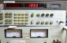
...until I stuck some large TV sweep tubes into a dead RF amplifier that used a 600 to 120 volt industrial control transformer in reverse as a power transformer. Unloaded B+ was in the 800 volt range. I wired a rather small (80 watt) OPT up to the tubes and started cranking it up. I was using an HP331A to measure the fun and somewhere beyond 160 watts, one load resistor shattered, and it's mate simply went open. At this point the OPT burst into flames, and the HP331A fried (smoke). Before I could recover from the panic, the diodes in the power supply shorted, tripping the breaker in the panel, and ending the fire dance.
There was a previous incident involving some computer power supplies that left parts of an electrolytic capacitor embedded in the ceiling. This left a large burnt spot in the workbench, so this was the wake up call.....
I installed a 15 amp circuit breaker for the work bench and a large red KILL button that killed all bench power when pressed. I also got a CO2 fire extinguisher and kept it under the bench in case the fire gods were ever summonsed again.
There were times when the bench breaker tripped, including the overdriven 833A test amp, a couple minor explosions where I smacked the button, and a few false alarms where I smacked the KILL button unnecessarily, but I never needed the fire extinguisher.
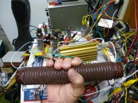
I did however upgrade my test load resistors since they no longer existed. I got the two big brown 8 ohm 500 watt resistors from Ebay right after the incident, which as was pointed out by someone more knowledgeable than myself are NOT non - inductive. Testing revealed that it really didn't matter below 10 KHz, and the error at 20 KHz was well below 1%, but I found the Gold colored Dales on Ebay rather cheap. They are good for 120 watts. I use them for "low powered" tests like squeezing 120 watts from those 13GB5's in the background.
In the 90's I made amps that were often sold, and as the OP states, if you want to sell it, it has to use tubes that you can buy at a guitar store, so that limited my power levels to about 75 watts per pair of Sovtek 6550's or about half that with the Chinese tubes. Many of my amps were simple singled ended designs based on the Fender Champ. I called them Turbo Champs at the time.
I had made a test load that used 4 X 8 ohm "non inductive" white cement resistors from Radio Shack all clamped to a fairly large heat sink in series parallel for 8 ohms total. This worked well, so I used it for years.....
...until I stuck some large TV sweep tubes into a dead RF amplifier that used a 600 to 120 volt industrial control transformer in reverse as a power transformer. Unloaded B+ was in the 800 volt range. I wired a rather small (80 watt) OPT up to the tubes and started cranking it up. I was using an HP331A to measure the fun and somewhere beyond 160 watts, one load resistor shattered, and it's mate simply went open. At this point the OPT burst into flames, and the HP331A fried (smoke). Before I could recover from the panic, the diodes in the power supply shorted, tripping the breaker in the panel, and ending the fire dance.
There was a previous incident involving some computer power supplies that left parts of an electrolytic capacitor embedded in the ceiling. This left a large burnt spot in the workbench, so this was the wake up call.....
I installed a 15 amp circuit breaker for the work bench and a large red KILL button that killed all bench power when pressed. I also got a CO2 fire extinguisher and kept it under the bench in case the fire gods were ever summonsed again.
There were times when the bench breaker tripped, including the overdriven 833A test amp, a couple minor explosions where I smacked the button, and a few false alarms where I smacked the KILL button unnecessarily, but I never needed the fire extinguisher.
I did however upgrade my test load resistors since they no longer existed. I got the two big brown 8 ohm 500 watt resistors from Ebay right after the incident, which as was pointed out by someone more knowledgeable than myself are NOT non - inductive. Testing revealed that it really didn't matter below 10 KHz, and the error at 20 KHz was well below 1%, but I found the Gold colored Dales on Ebay rather cheap. They are good for 120 watts. I use them for "low powered" tests like squeezing 120 watts from those 13GB5's in the background.
Attachments
- Status
- This old topic is closed. If you want to reopen this topic, contact a moderator using the "Report Post" button.
- Home
- Live Sound
- Instruments and Amps
- KT-88s: To the Pain