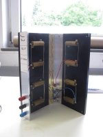
Have not even got this one warm yet. Total resistance is 20 ohms. Put a 25L6 on it to give a size reference. If need be I have a few more out in the shed.

Last edited:
So, along with my literature review (several chapters of RDH and finished Kuehnel's Guitar Amplifier Power Amps book), I've been thinking about this a lot. I note that of all the Beam Power Tetrodes that you could buy at a local music store, only the 6L6GC has extensive published characteristics for the grid-positive region, and those go to a higher positive voltage (+20 V) than any other such Beam Power Tetrode.6L6 has positive grid curves.
...
6L6 does not sport "limits" on grid abuse, but does have an AB2 suggested condition. Assume it is about as extreme as the developers thought was wise, and the big tubes will take more but maybe not double.
I saw that for the 6L6GC, the plate characteristics for the postive grid region and the plate characteristics for different screen voltages were identical, at least to my eyes. All of these curves start at the origin at the bottom left corner of the graph, follow the diode line up and to the right, have a knee that begins at some point on the diode line and ends at the beginning of an upward-sloping but mostly horizontal line.
When I say I identical, I mean that I would expect that plate current-voltage curves for Eg2 = 250 V and Eg1 = +15 V and for Eg2 = 400 V and Eg1 = 0 V to be within a few milliamps of each other, at every point from 0V to 500 V on the plate.
I also observed that for the families of grid characteristic curves, the distance between the curve for the negative grid voltage closest to zero and the zero grid curve was no greater than the distance between any two curves for positive grid voltage, provided that the difference in grid voltage was the same for any two curves compared.
That last paragraph expresses a simple concept that is difficult to put into words, so let me explain further. Suppose there is a curve for Eg1 = -2 V, and at every place along the curve, it is exactly 20 mA below the curve for Eg1 = 0 V. There will then be at least 20 mA between the curves for 0 V and for +2 V, and at least 20 mA between the curves for +2 V and for +4 V, and so on up to +20 V. That means that as a rough approximation of the plate curves, you can just take the first curve below the 0 V curve, measure the distance, multiply by the relative difference in grid volts, and voila! You now have a good estimate of the plate curve at any postive grid voltage (within reason). Sometimes the spacing between curves "opens up" a little bit as grid voltage becomes more positive, but I don't think it does so enough to invalidate this concept.
Note that it doesn't work the other way, because the curves "bunch up" as cutoff is approached on the bottom end (large negative values of grid voltage). The "bunching up" on the bottom is much more significant than the "opening up" on top.
And that's how, for a 6L6GC, I got to "Eg1 = 0 and Eg2 = 400 is the same thing as Eg1 = +15 and Eg2 = 250". Well, perhaps Eg1 = +14.5 V, but you get the idea.
I think started looking at screen current. There's a lot of interpolation involved, and I wouldn't bet the ranch on my results, but it sure seems to me like for a given operating point, screen current is about the same. Let me try to explain that.
Let's say you have a curve for Eg2 = 250 and Eg1 = 0. You can "raise the curve" by either raising screen voltage, or by raising grid voltage (positive values). Does it make a difference with regard to screen current? I don't think it does. As far as I can tell, the curve for screen current is the same for the case, Eg2 = 400, Eg1 = 0, as it is for the case Eg2 = 250, Eg1 = +14.5. It's certainly true to the first significant digit, but I wouldn't hang my hat on it being true for any digits past that.
And knowing that, it's a matter of "pick a curve for plate current as a function of voltage, and you have a good rough idea of what the screen current will be, regardless of whether that curve is a positive grid voltage curve or not". Pretty useful for my purposes.
As you surmised squeezing max power out of any pentode stresses the screen grid. You can relieve some of this stress by driving G1 positive and lowering the voltage on G2.
What he said. The screen current may stay the same, but Eg2 can be much lower, by hundreds of volts, so you can lower screen dissipated power by trading screen voltage for grid voltage.
So, what about grid dissipation? I don't have any specs for the limit, but I would guess that so long as there wasn't serious interaction between the grid and cathode, it should be able to dissipate at least half the power the screens do. Looking at the 6L6GC curves for grid current, it appears that even at +20 V, it runs at less than 1 watt until you start getting to the left of the page, where plate voltage is low. The curve rises so sharply that it appears to me that you pay dearly in terms of grid current (and watts) for each additional volt of plate swing. The saving grace is that at the plate current levels I'm looking for, the diode line keeps me from swinging too far to the left. That means I can also play off grid-screen stress vs. plate stress by rotating the load line - clockwise to spare the grids and screens, counterclockwise to spare the plates.
So, from all this, some operating conditions are starting to emerge. I don't see any obvious reason why the KT-88 won't play with the same +20 V on the grid that someone plotted for the 6L6GC decades ago. Some reason might emerge in testing, but for now, it's not clear to me that +20 V will break anything or necessarily sound bad.
Taking the KT-88 datasheets, and guestimating where the +20 V curve would be for a number of different screen voltages, I estimate that Eg1 = +20 and Eg2 = 100 doesn't give me enough plate current (well under 400 mA), that Eg1 = +20 V and Eg2 = 150 gets me there (up near 500 mA), and that Eg1 = +20 and Eg2 = 200 runs the screen current high enough to cause me problems.
Maybe I should back up and say that this only works if the screen voltage cycles with the input signal, such that it "gets a break" whenever the tube is in cutoff. We're talking 16W peak screen dissipation, which becomes 8W average with a square-wave input.
I think I need to "bias" Eg2 in order to stay in Class AB and not slip into Class B. I compared 6L6GC and KT-88 curves, and found that they both cutoff at almost the exact same grid voltage for a given screen voltage: -25 V for Eg2 = 150 V, -16 V for Eg2 = 100 V. I'm guessing that the KT-88 will also cutoff at Eg1 = -8 V, Eg2 = 50 V, which is the lowest curve I have for the 6L6GC. I'm not sure I want to go below that for a bias condition; I think I'd be getting too close to Class B operation.
At Ea = 800 V, Eg1 = 0 V, Eg2 = 50 V, idle dissipation at the plate would be about 19W (well within the 35-42 V spec for a KT-88), and screen and grid dissipation would be inconsequential. Of course I am soft on that 800 V due to the concerns that have been raised here, but regardless, the numbers all seem to work. I still have to set B+ and Za-a, but screen and grid operating conditions are starting to make sense to me.
To wit, Eg1 idles at 0V (roughly), and swings +20 postive during the conducting cycle and -20 when cutoff.
Eg2 idles at +50 V, and swings up to +150 and down to -50. I believe cutoff would occur at Eg2 = 27.8 V and Eg1 = -4.4 V. Each half of the push-pull pair conducts for 233 degrees out of the cycle, which I hope is sufficiently far into Class AB to eliminate crossover distortion. If it isn't, I could always put some positive bias on Eg1, which is...weird, but I don't see any obvious reason why that would blow something up.
I would like to have separate bias controls for each side. For twin/crazy drive, I'm not sure whether I should have adjustable bias on the screens or on the grids. Now that I've finished Kuehnel's book, I plan on hitting twin/crazy drive threads here.
This concept has been explored further in recent years, and it seems that running G2 at some positive idle voltage and full drive signal with a resistor divider between G2, G1, and ground to scale the drive to G1 is the way to go here.
I'm currently thinking of an interstange transformer with two secondaries, one for the screens and one for the grids. I realize that is probably overkill and that I'm just being paranoid about controlling inputs to each separately, along with separate quiescent bias conditions. But it should solve the drive problem!
> Eg2 = 250 V and Eg1 = +15 V and for Eg2 = 400 V and Eg1 = 0 V to be within a few milliamps
You have digested a fact that few tube abusers ever reach. *To a first approximation*, G1 and G2 have the "same" effect, except G1 is Mu times more sensitive. (Mu of 6L6 is about 10.)
You also see this from early to middle Fenders. When the 5881 6L6-replacement allowed Vg2=400V, Fender raised Vg2 and lowered load to get more power without distressing G1 current: 5F6a.
If you take this thought too far, especially by drawing current at both grids, the electron trajectories do not scale quite as Mu and you may heat your grids more than your speaker.
The current drawn by either grid in the positive region is directly dependent on the plate voltage. More positive voltage on the plate attracts more electrons to the plate.....why stick to a close by G1 at +20 volts, keep going, next comes G2 at say 300 volts....before the flying electron can slow down, it "sees" the plate in the 450 to 600 volt range and keeps going to it.
Now the peak of a signal crest comes along where we would like to pull that plate as close to zero volts as possible. Lets say that G1 is still at 20 volts, and G2 is still at 300 volts, but the plate is at say 30 volts, where is that electron going to land. It may hit G1 and stay there, but it's certainly not going to pass by a +300 volt G2 to get to a 30 volt plate.
When the plate gets below the voltage on G2, then G2 starts to suck a LOT of current. When the plate gets close to the voltage on G1, BOTH grids start to suck a lot of current.
Current through the grid is NOT what makes it glow, average grid power dissipation is. 50 mA drawn from G1 when it is at +20 volts is 1 watt, which is not likely to make a grid glow, but some claim it may damage a gold plated grid. 50 Ma from a 300 volt G2 is 15 watts, and G2 is glowing brightly!!!!
Average power is the power dissipated in a grid averaged over the whole audio cycle, so 15 watts on peaks is probably a lot less averaged when the amp is operated linearly, but it could be 50% of the time if the amp is slammed into hard clipping, so the grid still sees 7.5 watts average, and for most tubes, that's too much!
So far I have been slamming about +25 to +35 volts into G1 in a pair of EH KT88's with no ill effects. The tubes are triode wired which saves G2, but only makes about 75 watts per pair. I haven't done much real testing though. The amp is partially disassembled right now.
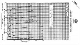
There may be a kinda-sorta partial exception to that statement. I have read a few claims that the 12AB5 is basically a 6V6 beam power tube (with a 12V heater) stuffed into a slightly smaller bottle with a 9-pin base, and slightly down-rated to account for the smaller surface area of the glass. And the 12AB5 data sheet does show curves for positive voltages up to +15 volts on the control grid (see attached image.)I note that of all the Beam Power Tetrodes that you could buy at a local music store, only the 6L6GC has extensive published characteristics for the grid-positive region, and those go to a higher positive voltage (+20 V) than any other such Beam Power Tetrode.
If the 6V6 is essentially the same as a 12AB5, it follows that one can expect similar behaviour from a 6V6...and it's certainly one of the few beam power tetrodes relatively easily found in a music store today.
To nobody's surprise, Tubelab George has already visited positive control grid voltage territory with 6V6s. The snippets I saved of one of George's posts says he reported 30 watts RMS at onset of clipping from a pair of 6V6, with 350 volts B+, 250 volts on G2, 25 mA quiescent current, and a 3.3k Raa output transformer. And, of course, MOSFET followers driving G1 to allow for AB2 operation. (No signal drive to G2.)
I plan to try something similar with a pair of 12AB5s one of these days, but other shiny objects keep catching my eye first. 😱
I also remember a few-years-old post by George in which he mentioned that "crazy drive" and heavy overdrive (as in guitar amps) seemed to be an unhealthy mix as demonstrated on his workbench: simultaneous huge positive signal swings on G2 and negative swings on the plates caused enormous increases in screen current, which heated G2 sufficiently to make G2 start emitting its own cloud of electrons, at which point the tube would experience runaway and die abruptly in a shower of blue sparks. 😱
-Gnobuddy
Attachments
The (self described) lunatic fringe of DIY HiFi liked to tube-strap pentodes beam & tetrodes, discovering both the effect you mention above and the nonlinearity that "solving" the problem with a resistor causes.... which heated G2 sufficiently to make G2 start emitting its own cloud of electrons, at which point the tube would experience runaway and die abruptly in a shower of blue sparks. 😱
The most elegant solution I saw involved a string of several 6.2V (IIRC for noise and temp stability) zeners, (suitably bypassed) and with a diode & small metal film resistor in series.
The diode stopped any reverse current flowing and the resistor acted as a fuse in the event of positive current run-away (screens being screens).
While perhaps not "tubelab_com-proof", the diode and/or "fuse" might be worth including in circuits pushing spec-sheet limits.
(Found my copy of the original by Bill Pearl. If you use a way-back machine you may be able to access the original at 404 Not Found)
Last edited:
So in Class AB2 we can drive the grids positive making more power. What do we use to create a limit for the tubes to obey so that it does not hurt itself too badly. In Class AB we have grid conduction acting as a diode limiting the drive voltage to roughly 0V. Where is the brake for class AB2?
That is certainly an elegant way to set G2 to a fixed voltage that's lower than the anode, and allow triode-strapping at the same time (voltage swings at the anode go through the zerners and show up undiminished at G2.)The most elegant solution I saw involved a string of several 6.2V (IIRC for noise and temp stability) zeners, (suitably bypassed) and with a diode & small metal film resistor in series.
I believe "crazy drive" is a much, well, crazier situation, because you have to drive G2 with an enormous input signal, since G2 is far from the cathode and therefore quite ineffective as a control grid. So on positive input half-cycles, you may be driving G2, say, 100 volts higher than it's quiescent voltage. And since you're driving both G1 and G2 positive, the anode responds by dropping to a very low voltage at the same time. So you now have an extreme case of the screen grid being maybe hundreds of volts more positive than the anode. 😱
If G2 gets hot enough to start emitting clouds of electrons, I am curious where they end up going. The anode is still at a positive voltage, albeit a low one...is that where all the electrons emitted by G2 will now go? That means a large current flowing between G2 and the anode, something that's not part of normal pentode / beam tetrode operation.
-Gnobuddy
I have been worrying about this exact problem for some time now, as I too plan to try some AB2 experiments soon.Where is the brake for class AB2?
I've thought of four different solutions, but they all have at least one downside. 😡
1) Supply the MOSFET drain with only, say, +15V DC. This means it can never drive the control grids more than 15V positive, which is safe for a 12AB5. The downside is that (as Tubelab George pointed out) at such a low drain voltage, the MOSFET reverse capacitance varies a lot with drain-source voltage, meaning it will change with the incoming drive signal. This may not matter at all for e-guitar, though, since we only care about frequencies up to 5 kHz, and don't care at all about small amounts of distortion (unlike for Hi-Fi applications.)
2) Put a resistor between MOSFET source and the control grid (G1) of the output tube, sized to limit maximum current flow into G1 to a safe value. Downside: the I-V curve for G1 current at positive Vgk is not going to be linear, which means the signal actually reaching the control grids will be distorted once into AB2. Will this sound bad for e-guitar? Will this sound good for e-guitar? I have no idea.
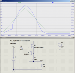
3) Add a sense resistor and NPN transistor to the source of the MOSFET to clamp maximum source current, in the same way that short circuit protection used to be implemented in solid-state power amps a few decades ago. The attached image shows the idea, which I'm sure you're already familiar with: if current through R1 increases enough for the voltage drop across it to turn on Q1, the gate of the MOSFET gets pulled down towards its source voltage, clamping the maximum current at roughly that value. Downside: will need some experimenting to find out what a safe current limit is, since the goal is actually to limit power dissipation in G1, and we don't know the current/voltage relationship there.
4) Limit the maximum drive signal arriving at the MOSFET gate using zeners or something similar. If the drive signal at the gate is, say, limited to +/- 15 volts max, then G1 of the corresponding output valve can never be driven to more than +15 V, since the MOSFET is a source follower with less than unity voltage gain. Downside: zeners seem to have a very, very soft knee at the sort of extremely low currents we would see at a MOSFET gate, so they make lousy voltage clamps in such a circuit.
I haven't tried any of them (yet), but my inclination is to try solution (1) first, because it's so simple. Maybe we'll get lucky and the MOSFET reverse capacitance will turn out to not be big enough to cause any real problems within the limited bandwidth of e-guitar. (Presumably, if necessary, we can just increase available drive current to the MOSFET gate until it's big enough to overcome any slew rate limiting and bandwidth limiting caused by Crss .)
-Gnobuddy
Attachments
The (self described) lunatic fringe of DIY HiFi
Who? Me? 🙂
The insanity started when Antique Electronics Supply started liquidating their NOS tubes for cheap in 2008. Lots of early high power experiments, schematics and test data can be found scattered throughout the thread:
Tube sale at AES
he mentioned that "crazy drive" and heavy overdrive (as in guitar amps) seemed to be an unhealthy mix
One of my most memorable experiments was when I blew the screen grid into pieces of burnt wire while extracting 120 watts from a pair of tiny 6BQ6GT sweep tube nearly 10 years ago. The driver mosfet was reduced to ash and a few other parts were dead too. That was actually done in pure screen drive. See post #5 in this thread:
Screen drive and other P-P experiments
In the years since that experiment I have been working on making big power without blowing tubes, or using complicated circuitry. Crazy drive was invented here, but I called it "dual drive." The schematic is in post #30
G1=G2/mu Scaled Drive Strawman Design
If G2 gets hot enough to start emitting clouds of electrons, I am curious where they end up going.
I figured this out in post #28 of the dual / crazy drive thread. You get G2 hot enough to glow while pulling that plate down to near zero, it stays hot when the plate zips up to 2 X B+ and BANG!
Post #28 in the G1 + G2 thread:
Observations discovered somewhere else in that thread (or maybe another one) found the limits of screen drive. As the screen is driven positive the plate is heading toward zero. When the plate voltage goes low enough and the screen voltage is high enough the screen will draw a lot of current, enough to cause it to glow brightly. As the plate voltage begins to return to a high positive voltage, that glowing screen grid will emit electrons that will travel to that positive plate resulting in a nuclear fireball inside the tube and lots of blown components! Dual grid drive may allow for more power without such bothersome side effects.
I have come to realize in the 10 years since all of this, that the same issue exists in normal G1 drive, screen drive, and "crazy drive." You are trying to pull the plate down to near zero. You need zero or slightly positive voltage on G1, and a substantial positive voltage on G2. G2 will draw serious current during this time. If it gets hot enough to emit electrons, a path for current flow from G2 to plate will exist on the next half cycle. A simple diode in series with the screen will block this path, but the hot screen grid problem remains.
"Normal" audio (guitar shop) tubes require high screen voltages to get low plate saturation voltage. Positive G1 (AB2) can help remove the stress form G2. High perveyance tubes (TV sweep tubes) do not have the high screen voltage requirement (work best at 150 to 175 volts), do not need or want positive voltage on G1, and make the highest power output of anything I have tested, but you can't get them at Walmart!
Look back at some of the testing in my early threads. Those 6BQ6GT's are about the same size as a 6V6, yet would make 60 watts of continuous sine waves for hours, lived at 110 watts, and blew up at 125 watts.
This what a 6V6 looks like inside after trying to make 60 watts per pair. This 6BQ6 was another casualty, sacrificed at 125 watts to understand whey they blew up in overdriven screen drive.
Attachments
Agreed - the Zeners based solution provides a better form of triode strapping, which is what the HiFi wonks want.That is certainly an elegant way to set G2 to a fixed voltage that's lower than the anode, and allow triode-strapping at the same time (voltage swings at the anode go through the zerners and show up undiminished at G2.)
I believe "crazy drive" is a much, well, crazier situation, because you have to drive G2 with an enormous input signal, since G2 is far from the cathode and therefore quite ineffective as a control grid.
Crazy drive is "just"* class B or class AB with healthy currents into both grids. Transmitting / PA-grade tube data sheets often have this mode listed**, either with cathode followers or tapped inductors driving the grids.
I've been pondering whether you can diode protect the grids in this mode and I think, as long as there's a resistive pull down to the nominal (idle) Vg, it should work. Perhaps. It will in class B, where both sides are idling at cut off. I;m still getting my head around an AB situation, as the diodes would cause the tube to stay at idle Vg, but with Va heading to twice B+.😱 Maybe a PTC instead?
I also need to have a think about what would happen with IT/inductive drive if one screen starts sucking current.
Back to my navel for a while.
* anyone who uses "just" in an engineering context is either lying, deluded or both.
** see my and Tubelabs references to the GE KT-88 and STC 807 data sheets early on in this thread.
Last edited:
The most elegant solution I saw involved a string of several 6.2V ... zeners,......That is certainly an elegant way to set G2 to a fixed voltage that's lower than the anode
Been there, tried that. Usually triode strapping a conventional audio tube by connecting the screen to the plate via a resistor works fine for HiFi. Most of the audio and "guitar store" tubes are rated for this mode up to a certain B+ voltage level, and have curves for it. Most guitar amp builders, and certainly all who are looking for maximum power, do not use triode mode.
Triode mode will always produce less power than pentode mode because as the plate voltage is pulled toward zero, the screen grid drops with the plate, reducing the tube's ability to pull the plate towards zero volts. AB2 helps in that regard, but now G1 sees more abuse to get more power since G2 is not doing it's share when it's needed most.
The issue arises when we want to triode strap a tube that has a significantly lower screen voltage rating than the plate voltage rating. I tried zener's and even gas regulator tubes in between the plate and screen in an attempt to lower the screen voltage, and thus run TV sweep tubes in triode. They have a max G2 voltage rating in the 200 to 300 volt range. This will result in a loss of power and some real ugly sounding clipping in the gas tube case. Why?
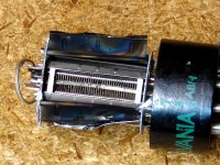
As the tube's plate is pulled toward zero the screen voltage now drops more quickly by the amount of voltage dropped in the zener string or gas tube. Now the point at which the screen grid can't do it's share is reached at a higher plate voltage, reducing power output. In the gas tube case, the screen current will drop below the level needed to sustain the gas tube, and it will extinguish resulting in zero power output. Picture shows a crude but effective test setup.
Work has been done by several "experts" over 10 or so years to overcome this issue, but no simple solution has been found. See this thread;
Adjustable distributed load discussion
Note the poster whose avatar is a cat is a well respected authority on tubes and has written several books on the subject.
This concept keeps resurfacing. I was recently asked about it in the Tubelab forum and shown an article from the 1950's on the subject:
Variable Triode-Ultralinear-Pentode modes?
Where is the brake for class AB2?.......I've thought of four different solutions, but they all have at least one downside.
Here is #5:
Put a resistor in series with the drain lead of the mosfet. Size it so that the voltage on the fet's drain will drop to say 25 volts when enough grid current flows to damage a grid. Assuming that G1 damage may occur at 1 watt (probably a conservative guess based on size of G1 VS G2), I aim for 2 watts.
This will keep the fet out of it's high capacitance zone for all but cases where the amp is clipping anyway. This should not impact the sound, and there are other ways to self limit the drive in a guitar amp. Note that a small cap (.1 to 1uF) can be used on the drain for momentary periods of excess grid dissipation so that transient sounds are not clipped.
Note that I have blasted several screen grids into scrap metal, but have yet to kill a control grid, so some of this may not be necessary, but I did use limiting resistors when testing my 75 WPC triode mode amp with rare and expensive NOS GE 6550's.
Why do I use 2 watt's after I just stated that 1 watt was max?
First off, we can bend, or flat violate some tube specs in a HiFi amp. This is because most listeners will not run their amps into clipping for long periods of time, and even if they did the AVERAGE power output over time is far less that max power. It's usually under 10% of max power, and that's when it is audibly clipping on peaks.
We don't have that luxury in a guitar amp. A guitar amp may see hours of abuse at power levels above the published ratings for the tubes being used.....Did Leo Fender violate the plate voltage specs on his 6V6 amps.....big time! Did his early 6L6GB amps run more than 270 volts on G2 and 360 volts on the plate??????
Experiments have shown that there are two over dissipation limits that must be considered in designing a high powered tube amp.
Maximum plate dissipation does not happen at full power in most every audio amp.
Maximum plate dissipation occurs at idle in a class A amp, since the amp is sucking full power from the power supply, but turning none of that into audio.
Maximum plate dissipation occurs somewhere near maximum power in a TRUE class B amp since it consumes zero plate power at idle.
Maximum plate dissipation occurs somewhere between idle and near full power in a class AB amp depending on how hot it's biased. It usually occurs somewhere between half and 3/4th's power for a typical class AB tube amp.
Maximum screen grid dissipation almost always occurs at maximum rated power output, and skyrockets when the amp is driven to clipping (above max rated power output). Here the output tubes are operating like switches, going from fully saturated to fully cutoff, so that little power is dissipated in the plate.
The screen grid is now eating full B+ (in many amps) or at some high voltage while it's plate is near zero volts. Here the screen is getting a large share of the cathode's electrons but is still at a high voltage, and therefore seeing very high dissipation.
An amp cranked to clipping is still switching between the two output tubes at a near 50% duty cycle, so that each output tube sees high dissipation for half the time, and near zero dissipation for the other half. This why we can stuff two watts into G1 for 50% of the time, it only AVERAGES one watt.
One can often SEE these effects. Some amps that run their tubes hard may show a pale red glow on their plates when operated at some midrange power level with a continuous sine wave. The plate will usually lose that color when the amp is driven harder. If the amp is pushed even harder, well into clipping the screen grids may begin to glow. Operation with screen glow will kill the tubes in short order.
Continuous sine wave testing is WORSE CASE for a HiFi or guitar amp, and continuous operation of some commercial amps in heavy clipping could result in blown parts.
There is a worse than worse case scenario with some guitar amps. Say an amp with a master volume control is pounded with a pedal board and adjusted such that the preamp is generating near square waves, then the master volume is turned up such that the power amp is just at clipping. Here everything is stressed since the peak and average power are the same. There are no rounded edges or "sine like waves" in the signal, only square waves alternating each tube between zero and full dissipation.
This can be measured on any given amp, and I am enclosing a spread sheet that I make when exploring the upper limits of a tube. Data like this should be collected on any amp design, but especially one that hits the tubes hard. You need to know where the problem areas are before tubes start blowing.
I have done this with several small tubes and will expand the chart to more to cover G1 effects and add bigger tubes in the future. This chart is for the 50C5, a common output tube from 50's and 60's table radios, and seen in some budget guitar amps of the day. The GE data sheet is enclosed.
First off I note that this tube is intended for use in class A output stages for table radios. It also has a "hot cathode" and claims high efficiency. These are things we want when squeezing maximum power. This little tube has a 50 volt 150 mA heater, 7.5 watts. The MUCH LARGER 6550 has a 10 watt heater. Which cathode puts out more electrons per square millimeter? This is important for minimizing the voltage drop across the tube when cranking maximum power.
Radios in that time period were often left on for several hours a day, and were often housed in plastic boxes with poor ventillation. The "typical operation" data IS AT MAX spec, yet the tubes lasted for years, so the specs are likely conservative. The plate in the 50C5 is actually a little larger than the plate in a 6AQ5, which is rated for 10, 12, or 13 watts depending on whose spec you read. Can the 50C5 eat 12 watts?
Testing reveals that red plate occurs between 16 and 19 watts depending on tube, so 10 to 12 watts is probably OK. I tend to believe the screen voltage rating, and will only bend it a bit if the dissipation is kept below maximum. The plate voltage spec in most tubes are very conservative, and often the socket is the limiting factor.
I set up a test amp to beat on several of these little tubes in AB2 to see what I could get. The 50C5 was chosen based on its hot cathode. I have similar data on several small cheap tubes. I tested several sets of operating parameters to see what I could squeeze out of these little guys. The 340 volt data is provided here. Two tubes of different brands were tested.
There is a tradeoff between idle dissipation and plate supply voltage. You can often crank up the plate voltage higher and higher to get more power output, however you must reduce the idle current to keep the idle dissipation to a reasonable level. I'm running the plate at 2.5 times it's rated maximum voltage, but I have to run the idle current down to 15 mA to avoid meltdown. There will be a point where you must trade off plate voltage VS idle current, and crossover distortion may be the limiting factor. That's the case here. I had these guys to 425 volts without issue, but you need to run them at 10 mA and they have too much crossover distortion at that low bias current.
Look at plate dissipation VS power output. In both cases the dissipation is the highest at around 15 watts. In both cases the screen dissipation increases as the power increases. The top tube goes over the 1.25 watt screen spec at 27 watts output. The bottom tube hits 1.25 watts at 31 watts. In both cases the screen dissipation tracks the distortion, and passes the spec at about 3% distortion......do we run our guitar amps over 3% distortion......
Some means of limiting the screen dissipation is needed to prevent meltdown.
Tubelab_com
Any chance you can post that spreadsheet? I've been gathering parts to clone your tubelab3. I have a little 50c5 PP amp, and I'm seriously interested in reproducing your test.
Sorry, dont mean to get off topic, please don't let this stall the conversation
Cory
Any chance you can post that spreadsheet? I've been gathering parts to clone your tubelab3. I have a little 50c5 PP amp, and I'm seriously interested in reproducing your test.
Sorry, dont mean to get off topic, please don't let this stall the conversation
Cory
And I was thinking of something as inelegant as a string of diodes to clamp the voltage in 0.7V intervals.
Stalling us by going off topic? You don't know us very well do you?Sorry, dont mean to get off topic, please don't let this stall the conversation
Cory
you can post that spreadsheet?
At the moment I have been making manual measurements, one data point at a time and writing them down on paper, IF the results were worth keeping. The reasons for this are more for a benchmark that anything else......
There was a thread involving Printer 2, Gnobuddy, myself and others where I kinda went off thread discussing these stupid high power results I was seeing while testing some tiny tubes. I believe that it was about a year ago, but I don't remember the details and can't find that thread now.....If either of you remember, please post a link here.
It seems that we were discussing budget guitar amps, and I mentioned the complex power supplies needed for AB2, and wondered if there was a better way. I went off on a road traveled years ago that resulted in many blown parts and a lot of frustration back then, but this time I have it almost perfected......hence the small cheap tubes and the standard bench marks to use for comparison to the "new stuff." Work is progressing with BIGGER tubes!
So far I have only tested some small 7 and 9 pin tubes that can be found cheap. Only a few data points that seemed interesting to me made it to the spread sheet. There are more hand written paper notes, but I would like to automate some of the data gathering before taking up a lot more time testing tubes.
Here is the excel sheet for 5 small tubes. Note that the 6GC5 IS a 6W6 in a fat 9 pin bottle. The 6W6, 12L6, 25L6, 50L6, and 25W6 are ALL THE SAME except for the heater voltage, so the 6GC5 data will apply to any of them. Yes, you can get 40 watts from a pair of 50L6's. The 6AQ5 is a crap shoot. Some will crank out 30 to 35 watts per pair without any stress, but some should be kept below 30 watts. These old round tubes were hard to assemble and many are not collinear. If you see one red spot on the side of the round plate, don't push it. The internal alignment isn't perfect.
The forum won't eat an XLSX file so I zipped it.
Attachments
We meandered about so as to where to start reading? As I said, off topic? 5E3 Blackface Single End Amp
The 6AQ5 is a crap shoot.
Lynn Olsen found some similar variations in the 6W6 (he was triode strapping them)
Lynn said:Well, after testing for distortion, beware the Japanese variant of the 6W6, which has more gain and 15 to 20dB more upper-harmonic distortion than the genuine article. The old-stock American and Italian versions were OK in performance, maybe a little worse than a 2A3, but certainly usable.
the 12w6 and 12en6 are look alikes of the 25l6 and are good sounding tubes, i used them in a pp amp...
in fact i made a guitar amp out of the 12w6 and guess what? it was chosen instead of a 6bq5....go figure..
in fact i made a guitar amp out of the 12w6 and guess what? it was chosen instead of a 6bq5....go figure..
- Home
- Live Sound
- Instruments and Amps
- KT-88s: To the Pain