If the basis is not OK it will never be OK. The shortest path to good results is doing stuff according conventions that others that were here before us have proven. Everybody can also learn from the mistakes of others and does not necessarily have to make these errors oneself. If one chooses to, like you do, it will take many hours to correct self made errors (and it costs other peoples time as well). This is nice once but the device will be a corrected case of errors. If the goal is to build sound well designed devices without too much errors and thus reach highest obtainable results then it would make sense to learn the basis and theory. All the issues that have occurred will then not be created but avoided and only a few unforeseen issues may occur which are then simply small challenges. In reverse: what sense does it make to burn hours and build something mediocre performing as it does not even do 20 Hz to 20 kHz (like now)?
If the basis is known problems become issues, issues become easy to solve, you will be answering (also to yourself) instead of asking. The dots of various technical matters will connect themselves when applying theory and practice. You will transform from "doing something" to "knowing something"")
If the basis is known problems become issues, issues become easy to solve, you will be answering (also to yourself) instead of asking. The dots of various technical matters will connect themselves when applying theory and practice. You will transform from "doing something" to "knowing something"
Last edited:
Goodness -- sure didn't think my little capacitive reactance answer would be whacking a hornet's nest.
I kinda liked PRR's tip -- and figured gregas could put it to good use.
Sorry to drag you back into this, jean-paul. We certainly have been around and around on several of these points, haven't we?
Regards
edit: DEFinitely an excellent link -- the 'RC Low Pass filter ..' -- especially all the other great stuff at the bottom!
Last edited:
Yaah, sorry -- I didn't organize that very well, eh !?
Probably, start with the 4,7uF 50V input coupling capacitor. Be sure to take it from the MUSES volume control, not AFTER the 0,047uF coupling cap going to the valve grid.
Then lower the HPA gain: All you have to do is tack a 470 or 560R resistor across the 10k feedback resistor (R2 - pin 6 to pin 2). That'll cut the gain to a little over 3dBV, which is plenty since the AD817 can only drive a 32 ohm load to about 1,1Vrms.
At this point you should have a listenable HPA. There may still be hum, but it should be relatively in the background. And the distortion should be fixed.
And here's something else I forgot earlier -- a little protection for the volume control.
Regards
Rick,
I don't think I can add those diodes. The volume control is mounted on a board. I connected +15v on one pin and -15v on another pin of header.VCU, Hi-End MUSES(R) Micro Volume Control Board (No controller needed) | academyaudio
Last edited:
@Rick PA Stadel: we do but we don't do it for nothing I hope. I don't like the diode protection at the inputs though, I would never use that and measure to check if it is necessary at all. I don't think it is necessary as the wiper is a low Z point and DC offset will only give a pulse at power on. It would be nice to know what the last part in the MUSES volume control is. If it is a resistor to GND then there will be a path for the caps to charge (assumption, best followed by measuring).
Rules of thumb and such are OK but only when one knows enough to use them. Not to skip a load of knowledge. I learned most dangerous people to be those that barely know enough.
Rules of thumb and such are OK but only when one knows enough to use them. Not to skip a load of knowledge. I learned most dangerous people to be those that barely know enough.
Last edited:
Yeah, the MUSES IC surely has its own transient / static protection internally.
Didn't have them looked up in time, but was thinking of a low capacitance Schottky part, maybe a BAS70LT1 or, what's the BAT59 or BAT5x that's widely used.
Would that be enough less objectionable? I have a funny feeling this piece may have some hot-plugging to survive, sometime in its future ..
Nighty, night for me, for now.
Cheers
> Don't teach someone that already works in a plain wrong way not to calculate coupling caps.
I thought you bailed:
Sorry I could not resist posting this. lol
Just when I thought I was out...they pull me back in. - YouTube
I wanted that to but see a wrong method is used to make already wrong more wrong. Why effing around doing stuff not according technical and proven conventions?
You're just wasting your time on him. It's just ALL. Sorry.
p/s: OPamp+Tube amp = Fi-END (final end).
Hey Rick,
I think I have some 470r resistors. Not sure about a 4.7uf cap. I may need to order that. That cap goes from the volume control to the headphone amp input in series correct? It's meant to remove any dc right?
So you recommend trying out the AD817 chips and just lowering the gain, and not just using a different chip?
At some point I'll probably get a nicer set of headphones if the headphone amp works out well.
Yaah, sorry -- I didn't organize that very well, eh !?
Probably, start with the 4,7uF 50V input coupling capacitor. Be sure to take it from the MUSES volume control, not AFTER the 0,047uF coupling cap going to the valve grid.
Then lower the HPA gain: All you have to do is tack a 470 or 560R resistor across the 10k feedback resistor (R2 - pin 6 to pin 2). That'll cut the gain to a little over 3dBV, which is plenty since the AD817 can only drive a 32 ohm load to about 1,1Vrms.
At this point you should have a listenable HPA. There may still be hum, but it should be relatively in the background. And the distortion should be fixed.
And here's something else I forgot earlier -- a little protection for the volume control.
Regards
Yes, in series; and Yes, to remove considerable DC. Since the input stage of the AD817 is NPN transistors, and the ~3uA current will pull down on the 100k resistor, fit the '+' terminal to the MUSES pot and the '-' to the '817. There's nothing magically-special about the 4,7uF value. If you have anything from 0,47 to 10uF would be fine to try. Even lower values would work for a test, but will gradually have a noticeable low bass roll-off.
The offset will decrease quite a bit (by both the gain reduction and removing the DC bias caused by the valve), but will still be rather high -- around a couple hundred millivolts -- but should be OK to show considerable improvement for brief intervals. I'm working on designing an offset for it.
The main reasons for sticking with the '817 for now are, that this part has already been exposed to the indignities that come with this design. And we may learn more (hopefully) by seeing how far we can get with this part before adding another variable. It also avoids exposing a new part to the pitfalls that come with this circuit; this part has already suffered them.
Remember, it isn't entirely the AD817's attributes that are causing the problems.
Cheers
Last edited:
Hey Rick,
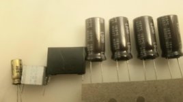
Thanks for the response. So I have some caps to choose from.
Nichicon Electrolytic 2.2uf 100v
Hitachi? film cap 1uf 100v
Panasonic film cap 1uf 450v
Nichicon Electrolytic 10uf 450v
I can do a test hookup and see what it sounds like.
So the coupling cap from the volume control to the input. The 470R added in parallel to the 10k r2 resistor. Also 220uf bipolar in series and 10k to ground on the output.
What do you mean by designing an offset for it?
Attachments
The 100V 2,2uF would do nicely.
The AD817 has a higher input current than this circuit was designed for -- about 3uA -- and it varies more over temperature than most.
With the 100k R3, it'll be in the 0,3V range; even with a more *reasonable*, say 22k value for R3, we can still expect ~70mV.
As soon as I get my brain wrapped around some fairly simple arithmetic, I'll post a 3 resistor, diode, and capacitor circuit that will compensate for a range of about 20°C, but only approximately.
Cheers
Last edited:
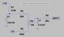
OK, here it is .. ( finally! )
Just a bit more messy than I had hoped, but pretty sure it'll work.
Should be good from about 20°C to 40°C (only).
R4 is a multi-turn trimpot. You can adjust it for zero output offset at an approximate mid-point of your regular listening room temperature. Or, if the chassis does some warming up, trim it out once the temp in the AD817's neighborhood reaches a stable value.
Only measure at the output, though -- the currents at the input are 10's of uA's, so probe loading will cause a shift.
Might be wise to cobble it up on a little separate bit of perf/Veroboard, since other op-amps will either not need it, or need something different.
Also, forgot to draw the 2nd 68k for the other channel; both can come off of C1 since each input only wants around 3uA. And C1 can be just about any value/type that doesn't have a ton of leakage: 0,1 to 10uF will all work.
Cheers
)Just a bit more messy than I had hoped, but pretty sure it'll work.
Should be good from about 20°C to 40°C (only).
R4 is a multi-turn trimpot. You can adjust it for zero output offset at an approximate mid-point of your regular listening room temperature. Or, if the chassis does some warming up, trim it out once the temp in the AD817's neighborhood reaches a stable value.
Only measure at the output, though -- the currents at the input are 10's of uA's, so probe loading will cause a shift.
Might be wise to cobble it up on a little separate bit of perf/Veroboard, since other op-amps will either not need it, or need something different.
Also, forgot to draw the 2nd 68k for the other channel; both can come off of C1 since each input only wants around 3uA. And C1 can be just about any value/type that doesn't have a ton of leakage: 0,1 to 10uF will all work.
Cheers
Attachments
Yeppers -- was just hoping to demonstrate the shortcomings of this op-amp choice in a way that even the signal-path-capacitor-haters out there couldn't complain about/object to ..
Must concede that it turned out a lot messier than it was in my limited imagination ..
Cheers
Must concede that it turned out a lot messier than it was in my limited imagination ..
Cheers
- Home
- Amplifiers
- Headphone Systems
- help with op amp headphone amp hum and distortion