I live in Rio de Janeiro, since 1977.
I spent some time working in SP and my wife's family is in BH, so we go there often. Well, not now, of course.
Fortunately we live in a good place by the beach, so when we go out to do something the view and weather are awesome.
The mess now, very bad thing in Brazil now is politics. We have probably the worst president in the world, which does not care for the health of the people. So we are forced to stay inside for protection. But as soon as things are better we plan to get a small place in Buenos Aires, Argentina, which is where I was born. If we are lucky to fulfill our plans, the idea is to spend long times in BA and not so long times in Rio. But who know what the world will be like until then.
These electronics projects are a good distraction, and I need to get my audio plans going.
I do not understand what you call the "linear regulator kit". What kit is that? The D-Noizator is a linear regulator, you do not need anything else.
What you can do is build one and compare the results with the other one. What changes in the listening.
When I look at the JC2, my interest is mostly as a line preamp, not headphone. I prefer speakers for daily listening. Used up all the headphone listening I would need when I worked as a pro location film sound recordist, and speakers is more my thing.
In any case I'm curious about buffering or line amplifying the power amps, and that's my interest about the JC2. How do they affect audio quality.
The mess now, very bad thing in Brazil now is politics. We have probably the worst president in the world, which does not care for the health of the people. So we are forced to stay inside for protection. But as soon as things are better we plan to get a small place in Buenos Aires, Argentina, which is where I was born. If we are lucky to fulfill our plans, the idea is to spend long times in BA and not so long times in Rio. But who know what the world will be like until then.
I love Buenos Aires as well -- incredible city. I have heard many negative things about Bolsonaro from my colleagues in Brazil. Many of them who were able to leave the country moved to the US or Europe. It seems this Covid crisis is just the latest example of his leadership failures.
I do not understand what you call the "linear regulator kit". What kit is that? The D-Noizator is a linear regulator, you do not need anything else.
Sorry if this wasn't clear -- I bought a cheap LM317/337 dual linear regulator kit at the same time that I bought the amplifier kit. I haven't received it yet. It was only a few dollars; maybe I will just purchase and build my own LM317/337 + D-Noizator circuit.
I also haven't received the amplifier enclosure. Just the kit and the transformer. So as I mentioned, I was planning to test it out w/ my bench power supply as a first step.
When I look at the JC2, my interest is mostly as a line preamp, not headphone. I prefer speakers for daily listening. Used up all the headphone listening I would need when I worked as a pro location film sound recordist, and speakers is more my thing.
I was planning on using this kit as a headphone amp as I already have a Korg B1 preamp in my stereo system. That said, I recently purchased a Focusrite 2i2 audio interface and would like to learn to use it to do some distortion measurements. So, it is my plan to eventually measure the distortion performance of the HPA w/ the audio interface after taking some basic measurements with the scope.
I agree these audio projects are a great distraction while in quarantine 🙂.
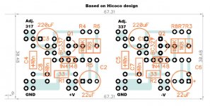
I took the trouble to design a Dinoizator assembly on a prototype pre-drilled board, that you can get anywhere.
So you can simply add it to the 317/337 kit you bought.
Or better yet, wait till I do the same with the Dienoisator, designed by and which simulates a lot better than Dinoizator.
What I did was use the pcb program, Diptrace, and use to place the parts. The traces are the part's wires, but you can do a clean job this way, instead of waiting for the pcbs to come.
I did that many times to prove a circuit worked and then have the pcb done.
Let's hope you understand what I did. The pcb is a standard size you can get on eBay. And I just showed the holes you will need.
Attachments
Bad relay in my kit?
Thanks for sharing this. I'll put this in the project queue (or wait for your Dienoisator version!). I have a bunch of double-sided protoboard PCBs I can use.
I'm hoping that Zung or someone else who has experience with the kit can weigh in on a little troubleshooting issue I'm having.
I built up the amp on the bench this weekend and biased it up using my lab bench supply. Biased fine, for now I'm running the JFETs at 2mA and tried the MOSFETS at 60mA and 80mA.
I don't have any output at the headphone jack. I think I have a bad relay.
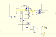
I found the schematic for the protection circuit from another amp by the same designer and verified that the voltages I am seeing on the IC are sensible. I have 12VDC on the coil of the relay. But it's not switching.
The signal from the amplifier appears on pins 4 and 5 of the relay. IIUC, with 12V on the coil, the relay should connect pins 2 and 7 (the pins that connect to the headphone jack) to pins 4 and 5, thereby passing the signal to the headphone jack.
Here's the data on the relay. I've attached the schematic I found of the protection circuit. Here's the datasheet for the UPC1237 IC.
The voltages on the UPC1237 are well within the parameters that should switch the relay (and - as I mentioned - since I have 12VDC on the coil it seems it's operating correctly and trying to engage the relay.)
Here are the measurements I took off the IC, followd by the threshold or reference values listed in the IC datasheet:
So - am I right about this? Bad relay? Or am I somehow missing something here?
I took the trouble to design a Dinoizator assembly on a prototype pre-drilled board, that you can get anywhere.
Thanks for sharing this. I'll put this in the project queue (or wait for your Dienoisator version!). I have a bunch of double-sided protoboard PCBs I can use.
I'm hoping that Zung or someone else who has experience with the kit can weigh in on a little troubleshooting issue I'm having.
I built up the amp on the bench this weekend and biased it up using my lab bench supply. Biased fine, for now I'm running the JFETs at 2mA and tried the MOSFETS at 60mA and 80mA.
I don't have any output at the headphone jack. I think I have a bad relay.
I found the schematic for the protection circuit from another amp by the same designer and verified that the voltages I am seeing on the IC are sensible. I have 12VDC on the coil of the relay. But it's not switching.
The signal from the amplifier appears on pins 4 and 5 of the relay. IIUC, with 12V on the coil, the relay should connect pins 2 and 7 (the pins that connect to the headphone jack) to pins 4 and 5, thereby passing the signal to the headphone jack.
Here's the data on the relay. I've attached the schematic I found of the protection circuit. Here's the datasheet for the UPC1237 IC.
The voltages on the UPC1237 are well within the parameters that should switch the relay (and - as I mentioned - since I have 12VDC on the coil it seems it's operating correctly and trying to engage the relay.)
Here are the measurements I took off the IC, followd by the threshold or reference values listed in the IC datasheet:
- Pin 1 - Overload detect - 0VDC (Vth values are .58-.76V)
- Pin 2 - Offset detection - 11mV (Vth .54 to .7VDC, -.12 to -.23VDC)
- Pin 4 - AC-off detector 1.4mV (Vth .6-.9V)
- Pin 6 - Output of relay - 12.1VDC
- Pin 7 - Vcc ON mute, setting delay time - 18.4mVDC
- Pin 8 - VCC - 2.4V (Vref = 3.0-3.8V)
So - am I right about this? Bad relay? Or am I somehow missing something here?
Attachments
You're way ahead of me, my board is not stuffed yet, and all my gears are boxed to move to my new place 🙂
But you can still do something:
But you can still do something:
- Measure the resistance of the coil (between pin 1 and 6) to see if it's anywhere near the published data (960-320 ohms). Depending on your DVM, you may want to reverse the probes and take a second reading.
- If the relay looks OK, turn on the HPA, and measure the DC voltage at "L Out" and "R Out": the output offset should be in the range of 1-100 mV.
- If the output offset is OK, connect some expendable earphones directly to the L-R Out to see if the HPA is working.
- If the relay is NOT OK, desolder it and try it with a bench supply or a wall wart. Worse case, replace it, and use the opportunity to fit an outboard XXL one, with silver contacts. This topic has been discussed at length in the CTC thread; do a search.
- If it were me, I'd monitor the offset over a few days/weeks. If it's stable, I'd short the relay out. But that's just me, don't do it.
Hey Zung,
Thanks for the quick reply --
1. Resistance of the coil is at about 730 ohms
2. DC offset voltage at L Out and R Out is +22mV and -19.1mV.
3. I already checked with a scope probe and a test signal -- HPA is definitely working. Nice clean sine wave at those relay pins, around 5.5Vrms or more before visible distortion / clipping.
4. I think I'll try this next. At no point does it go "click" in-circuit despite the 12V applied. I did watch the voltage rise somewhat slowly on the coil pins at turn-on though.
5. ...and then probably just do this so I can at least hear some music 😉
Quick update: I went ahead and jumpered the pins on the relay, and I have sound!
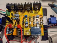
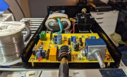
It sounds... nice. It certainly gets plenty loud. Lots of bass. Only had time to listen to a couple of songs on my usual pair of headphones after determining that the sacrificial pair survived being connected, so I haven't made any groundbreaking observations just yet.
Here's some pics on the bench in its test configuration. Forgive the mis-alignment of the leftmost MOSFET heatsink: this configuration is subject to change once I get the enclosure.
Attachments

Testing output power under load
I wanted to get a better sense of how well this amplifier could drive higher and lower-impedance loads.
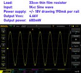
I did the following tests with ~80mA current in the MOSFETs and ~2mA in the JFETs. Bench supply with +/- 18V rails, and 190mA or so per rail (6.84W total power draw).
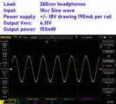
Tested with a 33ohm non-inductive thin film resistor dummy load to simulate my 32ohm Hifiman HE4XX headphones and a pair of 1975 Koss Pro 4/AA's (which InnerFidelity measured at 260ohms at 1KHz).
Results are attached measured just before clipping. Clipping - by the way - nice and symmetrical.
@33 ohms = 680mW
@260 ohms = 153mW
Hope some others may find this useful!
I wanted to get a better sense of how well this amplifier could drive higher and lower-impedance loads.
I did the following tests with ~80mA current in the MOSFETs and ~2mA in the JFETs. Bench supply with +/- 18V rails, and 190mA or so per rail (6.84W total power draw).
Tested with a 33ohm non-inductive thin film resistor dummy load to simulate my 32ohm Hifiman HE4XX headphones and a pair of 1975 Koss Pro 4/AA's (which InnerFidelity measured at 260ohms at 1KHz).
Results are attached measured just before clipping. Clipping - by the way - nice and symmetrical.
@33 ohms = 680mW
@260 ohms = 153mW
Hope some others may find this useful!
Attachments
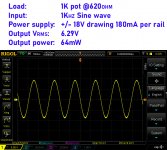
One more test - I wanted to see how this amp would do driving a really difficult load like a pair of 600 ohm headphones, so I tested it with a 1K potentiometer set to 620 ohms as a load (to simulate the Beyerdynamic DT880's as measured here).
64mW was the result -- see attached.
I also measured the amplifier unloaded and got 6.68Vrms -- so I calculate the ouput impedance to be about 15 ohms (depending on which numbers I use for the loaded voltage). This is an imprecise measurement since I am manually setting the just-before-clipping point but thought it might be interesting nonetheless.
Attachments
Last edited:
Next up, why don't you run some some distortion tests with REW or ARTA? Your built-in sound card should get you started, or, better still, find an el cheapo outboard USB box like the Focusrite.
Back to your original Q: if you have +12V at pin 6, it means the relay see 0V, so maybe it's something else.
Side Q: what do you think of the Hifiman HE4xx? I have the HE400S and think it's terrible, all bass and not much else, in spite of what InnerFidelity says.
Back to your original Q: if you have +12V at pin 6, it means the relay see 0V, so maybe it's something else.
Side Q: what do you think of the Hifiman HE4xx? I have the HE400S and think it's terrible, all bass and not much else, in spite of what InnerFidelity says.
Back to your original Q: if you have +12V at pin 6, it means the relay see 0V, so maybe it's something else.
Ah yes I understand -- should have realized that before.
While I was testing I noticed that if I short pins 7 and 8 together on the IC, the relay clicks (and voltage on Pin 6 drops, creating the voltage difference across the relay coil). I'll keep digging and see if I can figure out what might be going wrong w/ the circuit. Pin 7 is labeled "VCC ON mute, setting delay time". Now I know at least that it's not a bad relay.
Next up, why don't you run some some distortion tests with REW or ARTA? Your built-in sound card should get you started, or, better still, find an el cheapo outboard USB box like the Focusrite.
Yes -- I'm planning on it. I recently picked up a Focusrite Scarlett 2i2 and need to rig a cable together and experiment with the software.
Side Q: what do you think of the Hifiman HE4xx? I have the HE400S and think it's terrible, all bass and not much else, in spite of what InnerFidelity says.
I quite like them -- but I wouldn't recommend them if you don't like the HE400S, as I've read that the drivers are either the same or nearly so.
"Bright", "forward", "tilted-up treble" -- these sorts of descriptions are anathema to me. I prefer a laid-back presentation with good accuracy and detail but without sibilance and harshness. For me the HE4XX fits the bill. I don't find them overly bass-heavy; for me it's hard to imagine an open-backed headphone that would have an overwhelming amount of bass.
They're also very comfortable with the hybrid pads -- I wear them all day while I work at my desk. I did have to re-glue the pads though because they were coming apart (a common problem with the Focus A pads) after a little more than a year of gentle daily use.
I'm thinking of trying the Beyerdymanic DT880 600 ohm (or 250 ohm) with this amplifier. Any opinion on those, perchance?
... I believe I figured out the problem with the relay. The AC-Off detect on Pin 4 is expecting a voltage -- threshold is between .6 and .9V according to the datasheet. But the diode BD2 in the schematic (attached) is reverse-biased b/c I am feeding the amp w/ DC instead of AC voltage and it's being fed by the negative rail: therefore it isn't conducting and there is no voltage on Pin 4.
I'm imagine that this problem will resolve itself once I power the amp with the transformer instead of the my bench supply.
I'm imagine that this problem will resolve itself once I power the amp with the transformer instead of the my bench supply.
Attachments

I can confirm that the relay works fine w/ the AC supply -- I tested it over the weekend w/ the supplied transformer.
I'm in the process now of getting everything mounted to the enclosure. There's a fair amount of drilling and tapping involved. Not only did I need to drill out the front plate hole to be large enough for the potentiometer shaft, I'll have to drill out the knob as well.
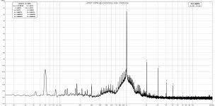
I've attached two distortion measurements. Take them with a grain of salt -- I'm not sure I really know what I'm doing yet, but I followed the advice in the Distortion Measurement with REW & Got Focusrite Scarlett 2i2 (2nd gen) for measurements. What's next? threads.
I'm using the line input on the Focusrite 2i2 w/ an Akitika 2PPM 1Khz oscillator as the signal source. These measurements were taken on the lab bench (a noisy environment) across a dummy load resistor while the HPA was powered by my lab bench supply (not the AC transformer). I left the sleeve of the unbalanced TRS cable I used unterminated per some advice in the other thread -- tip is connected to + and ring to ground. I think this is causing the cable to pick up additional noise (though advice in the Focusrite thread was to not terminate the sleeve so as to avoid a ground loop -- which may not be pertinent when not using the Focusrite as the signal source)... I'll do more distortion measurements once I have the amp in the enclosure.
Evidently, ~780mVrms is the sweet spot for the Focusrite so that's probably the more relevant of the two measurements.
I'm in the process now of getting everything mounted to the enclosure. There's a fair amount of drilling and tapping involved. Not only did I need to drill out the front plate hole to be large enough for the potentiometer shaft, I'll have to drill out the knob as well.
I've attached two distortion measurements. Take them with a grain of salt -- I'm not sure I really know what I'm doing yet, but I followed the advice in the Distortion Measurement with REW & Got Focusrite Scarlett 2i2 (2nd gen) for measurements. What's next? threads.
I'm using the line input on the Focusrite 2i2 w/ an Akitika 2PPM 1Khz oscillator as the signal source. These measurements were taken on the lab bench (a noisy environment) across a dummy load resistor while the HPA was powered by my lab bench supply (not the AC transformer). I left the sleeve of the unbalanced TRS cable I used unterminated per some advice in the other thread -- tip is connected to + and ring to ground. I think this is causing the cable to pick up additional noise (though advice in the Focusrite thread was to not terminate the sleeve so as to avoid a ground loop -- which may not be pertinent when not using the Focusrite as the signal source)... I'll do more distortion measurements once I have the amp in the enclosure.
Evidently, ~780mVrms is the sweet spot for the Focusrite so that's probably the more relevant of the two measurements.
Attachments

Build photos
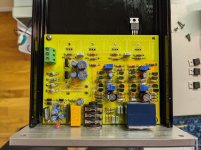
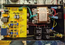
Last week I finished the physical construction of the amp.
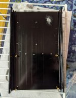
I drilled and tapped (by hand, with varying levels of success) holes for the PCB, transformer, and MOSFETs which are attached to the bottom side of the chassis. The chassis gets a little warm but not hot w/ 80mA of current in the MOSFETs.
My potentiometer is evidently not perfectly straight on the PCB, which causes some minor friction on the volume knob. Lesson learned here: PCB-attached potentiometers must be carefully aligned to protrude perfectly straight & centered from the chassis.
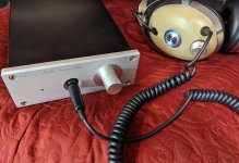
I picked up a set of 600 ohm Beyerdynamic DT880's and it drives them to high volumes with ease. Black background, no hum or hiss, seems to have good dynamics and bass reproduction. I'm happy with it. I'll probably leave the linear power supply as-is -- at least until the tinkering itch strikes me again. I'm thinking of building an OTL headphone amp to compare.
Last week I finished the physical construction of the amp.
I drilled and tapped (by hand, with varying levels of success) holes for the PCB, transformer, and MOSFETs which are attached to the bottom side of the chassis. The chassis gets a little warm but not hot w/ 80mA of current in the MOSFETs.
My potentiometer is evidently not perfectly straight on the PCB, which causes some minor friction on the volume knob. Lesson learned here: PCB-attached potentiometers must be carefully aligned to protrude perfectly straight & centered from the chassis.
I picked up a set of 600 ohm Beyerdynamic DT880's and it drives them to high volumes with ease. Black background, no hum or hiss, seems to have good dynamics and bass reproduction. I'm happy with it. I'll probably leave the linear power supply as-is -- at least until the tinkering itch strikes me again. I'm thinking of building an OTL headphone amp to compare.
Attachments
Thank you for sharing your build journal, the measurement and nice pictures. I enjoy reading it a lot. I hope your experience will encourage more to pick up this kit.Last week I finished the physical construction of the amp.
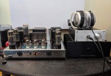
Just a side question. How do you like your Pass ACA class A amplifier? What do you use it for?
Last edited:
Hey keilau,
The ACA was my first amplifier build and I enjoyed learning on it. It sounds quite good here in a small room w/ big 3-way 90dB/1W/1M spec'ed speakers. Produces ample volume and satisfying imaging.
I will be the first to admit I am not particularly golden-eared, though, so I can't make any hyper-specific comments about the sound.
These days I do most of my listening on the VTA ST-70 pictured.
- Home
- Amplifiers
- Headphone Systems
- The JC2-HPA Headphone Amplifier