It means Amp Camp Amp on DIYaudio forum and is a kit offered by the DIY store.What's the ACA?
It can also mean Affordable Care Act passed by the Congress during the Obama administration. a.k.a. Obama Care. 😉
It is only 3300uF. What's the matter? And the THD is less than 3% at rated output. I do trust Nelson Pass' ears,Oh, it's one of those Pass designs with large output capacitor?
Not interested.
I agree with you. I have not tried a single ended power amp for 40 years. So I am in no position to comment. 😕
Last edited:
I just said I was not interested, but lots and lots of people have built those simpler NP designs and swear by them.
As I never had the chance to listen to one, my preconception is taking over.
Perhaps I should have kept my comment to myself, maybe it doesn't proceed. Sorry.
As I never had the chance to listen to one, my preconception is taking over.
Perhaps I should have kept my comment to myself, maybe it doesn't proceed. Sorry.
I am in the same boat as you are, not interested.I just said I was not interested, but lots and lots of people have built those simpler NP designs and swear by them.
As I never had the chance to listen to one, my preconception is taking over.
Perhaps I should have kept my comment to myself, maybe it doesn't proceed. Sorry.
I respect those user who think highly of ACA because they built and listened to it.
Back in business
It’s been a long time!
Exactly 1 year after moving to my new place, I’m down to only a couple of dozen boxes scattered all over; my ex-wife is hilarious whenever she visits.
Still, it’s time to get back in gear and tell the remainder of my story.
It’s been a long time!
Exactly 1 year after moving to my new place, I’m down to only a couple of dozen boxes scattered all over; my ex-wife is hilarious whenever she visits.
Still, it’s time to get back in gear and tell the remainder of my story.
The mods
First thing first: here are the stuff I don’t like in the kit, and my cures:
Erratum: in a previous post, I said the bypass cap I use, the red Chinese CBB 0.1uf and 1uF 100V were Polypropylene. They are not: they are Polyester, so not CBB which is Chinese for MKP. How do I know? Easy: use a hair drier to heat them up: the capacitance goes down with Polypropylene, and up with Polyester, by definition.
I chatted with a seller on Aliexpress, and he said “Red is CBB, green is MEF (Chinese for Polyester)”. Therefore, it’s the factories’ fault, using any color that’s inside the spray gun. Now I use the Wima instead.
First thing first: here are the stuff I don’t like in the kit, and my cures:
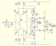
- FB cap: this has to go, replaced by a DC servo
- Bias spreader cap: this I’ll keep, for now
- Offset-balance: the upper (N-channel) drain resistor replaced with a pot
- A 47K resistor takes the place of the compensation cap to provide local FB
- The output source resistors should be lower, 1R is about right
Erratum: in a previous post, I said the bypass cap I use, the red Chinese CBB 0.1uf and 1uF 100V were Polypropylene. They are not: they are Polyester, so not CBB which is Chinese for MKP. How do I know? Easy: use a hair drier to heat them up: the capacitance goes down with Polypropylene, and up with Polyester, by definition.
I chatted with a seller on Aliexpress, and he said “Red is CBB, green is MEF (Chinese for Polyester)”. Therefore, it’s the factories’ fault, using any color that’s inside the spray gun. Now I use the Wima instead.
Attachments
Last edited:
DC Servo
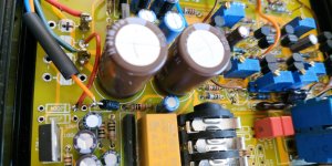
The DC servo is on a daughter board mounted on the main board with some soldering pins, see pic.
The Gerber is attached.
It needs V+, V-, Ground, In+, Out. “In+” is actually the output of the main board, taken from the junction of the 2 source resistors, and “Out” is the FB termination: I jumper the FB cap and solder the jumper to “Out”.
It has the provision for a basic +/- 15V Zener stabilizer for those who use higher supply lines. I don’t use it in mine.
The integration caps are 1uF Panasonic MKP with a 10mm pitch from Mouser , the opamp are the LF411 for now.
It works as advertised; the output offset is <1mV.
Attachments

Offset-Balance
There were some discussions about offset and drifts earlier, and the usefulness of a servo. My view is, even with negligible drift, adding a balance adjuster lets you compensate for the difference between the upper and lower half, and between AC and DC conditions. Just be carful not to overload the DC servo opamp.
The pots are mounted on the KFET (N channel) side in place of the drain resistors, with a tiny piece of Veroboard in between to make up for the difference in pitch.
In the same pic, you can see the feeds for the servo, and the shunt FB resistor in place of the compensation cap.
Attachments

Last edited:
Ground loop
This one took me forever and more to fix.
When I fired it up the first time, it hummed/buzzed like hell. I tried every combination I could think of, between the trafo, the PS regulator, and the main board, none worked. Finally, the culprit is (I think), some weird interaction between the on-board uPC1237 protection and the main circuitry.
Here’s the hack that works for me:
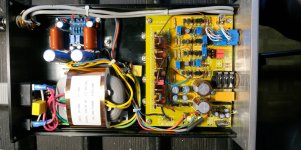
- Disable the extra rectification for the uPC1237: remove the two 1N4007 feeding the 7812 regulator, jumper it directly to V+ instead
- Remove all traces carrying AC from the main board: unsolder the anode of the 3rd 1N4007, the one for the power-off sense, and attach it directly to the trafo with a wire
- The common of the trafo, the input ground of the PS regulator, and the main ground of the main board all go to a central pseudo-star ground point, which connects to a ground loop breaker to the mains
- See pic
Attachments
Adjustments
The standing current of the JFet determines that of the VAS, which determine that of the MOSfet:
The standing current of the JFet determines that of the VAS, which determine that of the MOSfet:
- Disconnect the DC servo if implemented
- Set the additional drain pot to about mid-way
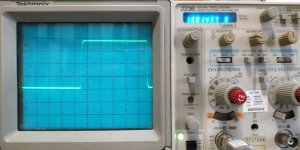
- Set the JFet drain current to 2mA: 1.36V across the 680R drain resistor
- Set the MOSfet current to anything over 10mA, just to make sure they conduct
- Minimize the DC offset with the Offset-Balance pot
- Reconnect the DC servo if implemented
- Set the MOSfet current to whatever value you fancy: I use 75mA. With the box I have, this gives a temperature rise of about 12°C above ambient and it takes a long time to get there, so re-do this after an hour or so.
- If desired, fine tune the distortion value and spectrum with the offset pot
Last edited:
Not sure if you are still using IRF MOSFETs at the output.
I would go for 2SK2013/2SJ313 any day.
Failing that, still prefer FQP3N30 / FQP3P20.
Patrick
I would go for 2SK2013/2SJ313 any day.
Failing that, still prefer FQP3N30 / FQP3P20.
Patrick
No, I reverted back to the 2SJ407/2SK2381... Don't scream! 🙂
I'll try the FQP3N30/FQP3P20 next time I place an order at Digikey or Mouser. For now, I'm enjoying my newly refurbished ESL57 more and more, and my Hifiman less and less, so I'm in no particular hurry.
I'll try the FQP3N30/FQP3P20 next time I place an order at Digikey or Mouser. For now, I'm enjoying my newly refurbished ESL57 more and more, and my Hifiman less and less, so I'm in no particular hurry.
If you want a super matched set of 2Sk2013/2SJ313 to try, get in touch by PM.
Won't be the cheapest you can find.
Otherwise NicMac still has plenty, I think.
Patrick
Won't be the cheapest you can find.
Otherwise NicMac still has plenty, I think.
Patrick
BTW your DC servo is so huge that it is almost criminal. 😉
I did mine all in SMD and you can fit it in the footprint of the DC cap.
Just use Panasonic ECPU 1µ / Susumu 0805 1M.
It is only DC servo; not in signal path.
Cheers,
Patrick
I did mine all in SMD and you can fit it in the footprint of the DC cap.
Just use Panasonic ECPU 1µ / Susumu 0805 1M.
It is only DC servo; not in signal path.
Cheers,
Patrick
A good signal "block" path takes almost as much effort as a signal "pass" path and deserves as much TLC.
And I like it big because at least I can see it. 🙂
And I like it big because at least I can see it. 🙂
- Home
- Amplifiers
- Headphone Systems
- The JC2-HPA Headphone Amplifier