Speaking of grounds, where does the yellow-green wire disappear to? Screwed to chassis, I assume?
Yes, to chasis.
Where did you find a -24V or so SMPS? Or does this one have a floating secondary side so you can still connect the mains filter to PE regardless of whether you're using it for + or -24 V?
I used something like this: https://www.mouser.es/ProductDetail/?qs=gTYE2QTfZfSVkZJLoEiANg==
Datasheet: https://www.mouser.es/datasheet/2/670/vgs-75b-1383908.pdf
Nothing of the other world but they are economic and serve perfectly for this task. I prefer this type of psu to wall chargers. I want to use something similar in my ACA too.
Thanks, I wrote down the reference. I thought you used the "Orange Drop" that are quite popular in guitars and guitars amps.
https://www.mouser.es/datasheet/2/88/225p-318236.pdf
Where did you find a -24V or so SMPS? Or does this one have a floating secondary side so you can still connect the mains filter to PE regardless of whether you're using it for + or -24 V?
This was discussed in posts #53 and #54. Here is a link , I hope I arranged the URL correctly.
T2 withSuperreg + Linear/SMPS PSU Options
The standard wallwart fed T2 was impressive, a neat and straightforward build that delivers very enjoyable sound. After listening to it for a couple of days I decided to see whether a linear supply and super-regulator would bring about improvements.

The Linear PSU is complete overkill but rather good.

Initially I used a Twisted Pair Placid HD set for 24 volts running off a bench supply, feeding the filter sections of the T2. This was a slight improvement over the wallwart SMPS but not as great as I had expected. Switching the Placid for an ALWSR gave a further improvement but there was more of an improvement when I bypassed the T2 filter section and fed 22v directly to the amps rails (re-biasing the output stage back to 150mA).

Then I built up a separate linear rectifier and cap multiplier from a 24v transformer. Finally I found an oversized 36volt transformer which I used with choke regulation. In spite of the downstream Super-reg each stage on this path improved the sound quality. Finally I tweaked the Super-reg with some extra filters and used remote sense.

The net result is a big improvement over the SMPS wallwart and T2 filtered version, but the cost is high, more than double the cost of the T2 alone. I'll also need another modushop case for the transformer and choke regulation.
I really want to be able to use both the Wallwart supply and the external linear supply at different times/places using the same single power input socket. To this end I reduced the voltage of the Super-reg to just under 18 volts by just adding an extra switched resistor (I'll use the front panel switch to operate this). The super-reg needs at least 5 volts of headroom. This reduced the output stage bias to 112mA but the sound was still better with the Wallwart and Super-reg than it had been at higher bias with just the T2 PSU filter.
I'm sure there are more improvements in supply to be had, particularly with respect to using the Wallwart. It would be good if I could integrate the T2 filtration into the power supply chain when the wallwart is in use. It may well bring further benefits when the linear PSU is used as well. I've got some small 3.3u polypropylene input caps to try and a couple of transistor based current sources to try in place of the E-153's but I want to be sure each is a real improvement so must be very familiar with the sound - so some serious listening is required.
Very nice bit of kit Mark. Thanks very much for its creation.
John
The standard wallwart fed T2 was impressive, a neat and straightforward build that delivers very enjoyable sound. After listening to it for a couple of days I decided to see whether a linear supply and super-regulator would bring about improvements.
The Linear PSU is complete overkill but rather good.
Initially I used a Twisted Pair Placid HD set for 24 volts running off a bench supply, feeding the filter sections of the T2. This was a slight improvement over the wallwart SMPS but not as great as I had expected. Switching the Placid for an ALWSR gave a further improvement but there was more of an improvement when I bypassed the T2 filter section and fed 22v directly to the amps rails (re-biasing the output stage back to 150mA).
Then I built up a separate linear rectifier and cap multiplier from a 24v transformer. Finally I found an oversized 36volt transformer which I used with choke regulation. In spite of the downstream Super-reg each stage on this path improved the sound quality. Finally I tweaked the Super-reg with some extra filters and used remote sense.
The net result is a big improvement over the SMPS wallwart and T2 filtered version, but the cost is high, more than double the cost of the T2 alone. I'll also need another modushop case for the transformer and choke regulation.
I really want to be able to use both the Wallwart supply and the external linear supply at different times/places using the same single power input socket. To this end I reduced the voltage of the Super-reg to just under 18 volts by just adding an extra switched resistor (I'll use the front panel switch to operate this). The super-reg needs at least 5 volts of headroom. This reduced the output stage bias to 112mA but the sound was still better with the Wallwart and Super-reg than it had been at higher bias with just the T2 PSU filter.
I'm sure there are more improvements in supply to be had, particularly with respect to using the Wallwart. It would be good if I could integrate the T2 filtration into the power supply chain when the wallwart is in use. It may well bring further benefits when the linear PSU is used as well. I've got some small 3.3u polypropylene input caps to try and a couple of transistor based current sources to try in place of the E-153's but I want to be sure each is a real improvement so must be very familiar with the sound - so some serious listening is required.
Very nice bit of kit Mark. Thanks very much for its creation.
John
John, congratulations on your successful build!
Also hats off to you for performing some very insightful experiments. Maybe you would find it easier to change things around further, if you mounted the amplifier PCB into a bigger chassis? Like perhaps the Galaxy but with 2U height, and greater depth (230 x 280 internal)? That way you can install lots of assorted PSU experiment boards, and accommodate any extra-tall electrolytic capacitors or heatsinks they might include. It would mean drilling your own front panel and rear panel on the new box, since the T2 predrilled PCB panel substitutes only fit 1U height.
Also hats off to you for performing some very insightful experiments. Maybe you would find it easier to change things around further, if you mounted the amplifier PCB into a bigger chassis? Like perhaps the Galaxy but with 2U height, and greater depth (230 x 280 internal)? That way you can install lots of assorted PSU experiment boards, and accommodate any extra-tall electrolytic capacitors or heatsinks they might include. It would mean drilling your own front panel and rear panel on the new box, since the T2 predrilled PCB panel substitutes only fit 1U height.
OK, got it. I'm still thinking about the potential implications when it comes to common-mode radiation over the power cord, however. If it were me, I'd be getting a portable shortwave receiver from the stash and see what that has to say on the matter.This was discussed in posts #53 and #54. Here is a link , I hope I arranged the URL correctly.
An X2 rated capacitor of maybe 22-100 nF from the power supply's PE connection to IEC PE may be in order. Should make the mains filtering feel a lot more grounded.
")
Presumably the mains filter has components going to the PE connection, and then there probably is a little Y class capacitor from PE to V-.
As someone who has been involved with shortwave listening for decades now I'm a bit paranoid when it comes to EMC - and for good reason, I dare say. It's a good thing I wasn't very active any more when I moved into my current apartment, as it has a tendency of being a cesspool of RF noise. Right now it's trying to convince me that the old "Woodpecker" (OTHR) is still active, but the source actually is somewhere within the house, possibly a PLC (HomePlug) affair (as the ham radio bands are conspicuously spared) in one of the apartments on the ground floor. I am so looking forward to nagging random people about their home networking... not. ;-/
The T2 tweaks and optimizations file suggests
I imagine a veteran shortwave listener like yourself, would enjoy it immensely.
If you wish to explore the world of very elaborate ferrite filtering, Google search for “Common Mode Chokes” by W1HIS also known as Chuck Counselman. Wow.
I imagine a veteran shortwave listener like yourself, would enjoy it immensely.
the sound is silly crazy good...I am gushing all over the place here its that good..
"I'll have what [he's] having".
I used these Vishay resistors from Farnell/Element14:
https://au.element14.com/vishay/pr03000206809jac00/metal-film-resistor-68-ohm-3-w/dp/4984389
They are showing some limited stock (135).
Arrow.com have some too:
https://www.arrow.com/en/products/pr03000206809jac00/vishay
Don't know if that is of any help.
https://au.element14.com/vishay/pr03000206809jac00/metal-film-resistor-68-ohm-3-w/dp/4984389
They are showing some limited stock (135).
Arrow.com have some too:
https://www.arrow.com/en/products/pr03000206809jac00/vishay
Don't know if that is of any help.
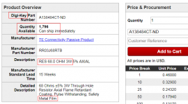
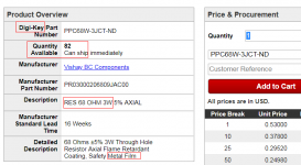
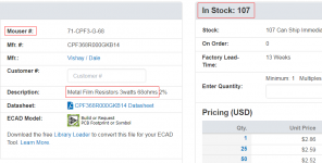
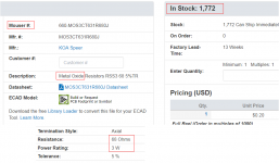
Here's what I found on the USA websites of DigiKey and Mouser. Saturday morning 08:50 NYC time.
_
Well that's embarrassing. Missed those on Digi-key. Thanks.
...I'm sure there are more improvements in supply to be had, particularly with respect to using the Wallwart. It would be good if I could integrate the T2 filtration into the power supply chain when the wallwart is in use. It may well bring further benefits when the linear PSU is used as well. I've got some small 3.3u polypropylene input caps to try and a couple of transistor based current sources to try in place of the E-153's but I want to be sure each is a real improvement so must be very familiar with the sound - so some serious listening is required...
Nice work, there is a lot to be gained with a Cap Mx as a power supply for a SE Class A amp. I made a board that accomplihses this plus has a spot for installing a TO220 voltage reg downstream of the cap Mx. Useful for using the TPS7A4xxx 4uVrms noise LDO. It just needs a walwart or some other source of DC input that is about 5v higher than nominal Vcc needed to account for the dropout fromt he cap Mx and LDO.
I seemed to need this ciucuit all the time and kept making them P2P until one day had a board made:
GB for Simple Cap-Mx Regulated Low-Noise PSU
Here is an example made by Gtose:
Simplifies need for a low noise single rail supply into 1 board.
Interesting XRK. There's a similar little cap multiplier circuit board that was developed over on Pink Fish Media. It has two sets of filtering and the same FETs. The problem with these FET's (for me) is that they drop a lot of volts. Here's a circuit I'm building up now (point to point) which reduces the dropout voltage to circa 3 volts:
.jpg")
The npn is a 2sc5171 and the load current is 370mA for the T2 and its regulator giving a base current of around 2mA.
The npn is a 2sc5171 and the load current is 370mA for the T2 and its regulator giving a base current of around 2mA.
Last edited:
Replacement Current source for T2
Here's something I tried a few days ago on the T2. It is a current source that requires less voltage and allows the removal (shorting) of the 1N4004 diodes. To my ears it sounds better than using the E153 even when the 1N4004s are left in circuit.
.jpg")
It allows as little as 2 volts between the current sink and the negative rail. The FET's require about 3.4 volts. I hard wired everything to the transistor legs as a three terminal device and fed the collector of the npn straight into the newly vacated +ve pad of the E153. I ran the 0v feed from the 0v end of C24/C74 and took the negative supply from the negative end of D24/D74.
Only a small adjustment is required to reset the biasing back to the 5.1volts. You can of course use other small signal npn's but the 2N5551's have a good balance of early voltage and Hfe. BC550's will not be as good. ztx651-3's are pretty good here too. A red LED would be OK or even a couple of 4148 diodes but adjust the emitter resistor for the lower voltage.
Reduces the overall PN junction count but defo not a two transistor T2 any more!
John
Here's something I tried a few days ago on the T2. It is a current source that requires less voltage and allows the removal (shorting) of the 1N4004 diodes. To my ears it sounds better than using the E153 even when the 1N4004s are left in circuit.
It allows as little as 2 volts between the current sink and the negative rail. The FET's require about 3.4 volts. I hard wired everything to the transistor legs as a three terminal device and fed the collector of the npn straight into the newly vacated +ve pad of the E153. I ran the 0v feed from the 0v end of C24/C74 and took the negative supply from the negative end of D24/D74.
Only a small adjustment is required to reset the biasing back to the 5.1volts. You can of course use other small signal npn's but the 2N5551's have a good balance of early voltage and Hfe. BC550's will not be as good. ztx651-3's are pretty good here too. A red LED would be OK or even a couple of 4148 diodes but adjust the emitter resistor for the lower voltage.
Reduces the overall PN junction count but defo not a two transistor T2 any more!
John
Last edited:
Hi I think the green LED in #215 might be drawn upside down.
Since this ckt replaces a 15 mA current regulator diode, you probably want to double check and verify that the voltage across the 82 ohm resistor, is close to 1.23 volts.
{Math: 0.015 amps X 82 ohms = 1.23 volts}
Since this ckt replaces a 15 mA current regulator diode, you probably want to double check and verify that the voltage across the 82 ohm resistor, is close to 1.23 volts.
{Math: 0.015 amps X 82 ohms = 1.23 volts}
Oops, sorry about the LED polarity. Thanks for pointing that out. Was built the right way round though, the LED's are lit.
Just measured exactly 1.20 volts after warmed up. That's 14.6mA and within the spec of the E153's. increases by only 3mV from cold. The E153 is specced over its voltage range at +/-3mA! The biasing barely needed touching when they were first fitted and when the 1N4004's were removed.
Now building a cascode for the input transistor to see if that makes any noticeable difference at all. I don't expect it will. I really need an objective measurement of the changes but all I have is a dual trace scope and a reasonably low distortion signal generator. May be able to detect changes in the harmonics of say a 20kHz input signal?
John
This am I listened to the Bottlehead Mainline, their TOTL headphone amp for the masses.
With my session with their Crack with Speedball the T2 IMO was a nicer overall presentation.
But with the Mainline the T2 comes close but the Mainline is still a nicer amp than the T2 IMO. The soundstage is similar to the T2 but the Mainline is even more wider, open and clear.
Now to be fair we are compairing a less than $200 amp to a $1299 kit amp. Bottlehead has really done a nive job with their amp...
...as well as Mark has done with the T2.
Still an awesome amp ...
Alex
Interesting post I have similar thoughts about the Whammy+Burson V6 Classic, minus C1&C5 (jumpers used) vs Mainline (+10uf RTI teflon output caps)
Going to shoot Mark a pm later see if he has any more pcbs available.
Interesting post I have similar thoughts about the Whammy+Burson V6 Classic, minus C1&C5 (jumpers used) vs Mainline (+10uf RTI teflon output caps)
Going to shoot Mark a pm later see if he has any more pcbs available.
I think the Mainline is one of the most expensive diy kits I've seen. I had to google and make sure it wasn't a pre-built unit of some kind. If the Mainline is $1300 as a kit, imagine what it would cost retail... If the T2 comes anywhere close to that I'm a happy camper.
Mouser BOM is about $85. PCBs from me cost about $20 (less inside USA, more outside USA). Chassis from diyAudio Store is about $50. Ultra sexy volume control knobs from eBay sell for about $10. So that's about $165 total. Plus incidentals like solder, alcohol wipe-down, etc.
- Status
- Not open for further replies.
- Home
- Amplifiers
- Headphone Systems
- Single ended class-A headphone amp using two transistors: T2