Maybe add 200R resistor in series with output (this will also have effect of increasing Q of phones and may give deeper bass)? I know that playing around with resistor values on gate may have an effect. I will have to play with it.
Hi X,
The beauty of the BF862 is their high transconductance so inserting a 200 ohm at the output will lower the DF like crazy ruining the nice transconctance effect of punchy bass, I might be wrong but I think the bass would be bloated and not punchy. I read quite often that the series resistor with the output should be around 1/10 your cans impedance.
Thanks,
Eric
X,
My thoughts on jfets are these.
Know first the Idss of the device. Once you have this, select 2/3 of this value for your circuit.
When you have your drain and source values, you then select the upper, bias voltage resistor. In your circuit it is 22R. Knowing you are gunning for 10mA, 2/3 of 15mA, you then select the bias voltage resistor to deliver the expected 10mA. Through the 1k drain, you measure off 10V, reducing the Vcc to 8V.
Once you have it running, check the voltage between gate and source. This is the bias voltage, and it should be between -0.1 and -0.3 volts for best linearity. It is this transfer function which drives the harmonics in the distortion.
I think you have the correct point on the BF862. You do not to be quite careful with the operating point of the LU1014D, because it is self-biasing as it is in source follower mode.
Eric is right too. Put a 47R-100R in the gate stopper of the LU1314D, but don't use a resistor in the output to the headphone. You could use maybe 10R to reduce danger of a short, but no more.
HD
Hi X,
The beauty of the BF862 is their high transconductance so inserting a 200 ohm at the output will lower the DF like crazy ruining the nice transconctance effect of punchy bass, I might be wrong but I think the bass would be bloated and not punchy. I read quite often that the series resistor with the output should be around 1/10 your cans impedance.
Thanks,
Eric
Actually it's the LU1014D but you are right it's not good to load it in series with too much R. Hugh just gave tips on where to tweak for harmonic signature. Bias of the gate to source is what controls that.
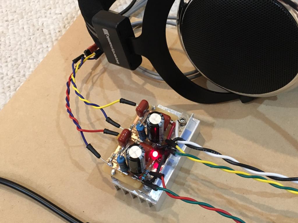
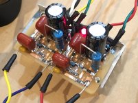
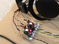
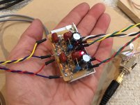
Aksa-xrk971 JFET HA works!
I just finished the amp and fired it up just minutes ago. It's a miracle it works the first time with no smoke or fire. I am using a 19.5v 4.65amp SMPS laptop brick for PSU raw (no filtering for now).
The board is so small, it was kind of a challenge to squeeze some of the through hole components in there. Juma recommended a 470uF output cap so I am using a rather dubious brand (as cheap as they come from China Chenxing brand 470uF 50v 105degC) but bypassed with 1uF 100v MKT. On input I have same 1uF 100v MKT paralleled with 10uF 50v MLCC to get the deep bass. I ran out of 47R SMT so using 39R gate stoppers. The source resistor is a metal thin film 100R 2w mounted vertically to fit. The LU1014D's are very securely fastened with a small L bracket clamp held in place with four 6-32 hex cap screws pressing down on power JFETs against silicone transistor pad.

It is a tiny amp! Look at the scale relative to the headphones. I am measuring 104mA bias current per channel. That's basically 19.5v x 0.104A = about 2 watts dissipation per channel or 4 watts total. Heatsink seems appropriately sized, hot but not unbearable to touch. I can hold it for over 20 seconds before it is uncomfortable.
I am listening to the usual YouTube dance mixes to give it some time to burn in. Sounds quite nice. Very clean and excellent sonic presentation. Bass is very good.
I will post detailed listening impressions soon - but so far so good. That laptop SMPS works surprisingly well. No fuss no muss type of PSU for a head amp 🙂
Edit: you have to see this thing to believe it - how such beautiful powerful sound can come from such a small two transistor amp? Here it is singing in my hand!

I just finished the amp and fired it up just minutes ago. It's a miracle it works the first time with no smoke or fire. I am using a 19.5v 4.65amp SMPS laptop brick for PSU raw (no filtering for now).
The board is so small, it was kind of a challenge to squeeze some of the through hole components in there. Juma recommended a 470uF output cap so I am using a rather dubious brand (as cheap as they come from China Chenxing brand 470uF 50v 105degC) but bypassed with 1uF 100v MKT. On input I have same 1uF 100v MKT paralleled with 10uF 50v MLCC to get the deep bass. I ran out of 47R SMT so using 39R gate stoppers. The source resistor is a metal thin film 100R 2w mounted vertically to fit. The LU1014D's are very securely fastened with a small L bracket clamp held in place with four 6-32 hex cap screws pressing down on power JFETs against silicone transistor pad.
It is a tiny amp! Look at the scale relative to the headphones. I am measuring 104mA bias current per channel. That's basically 19.5v x 0.104A = about 2 watts dissipation per channel or 4 watts total. Heatsink seems appropriately sized, hot but not unbearable to touch. I can hold it for over 20 seconds before it is uncomfortable.
I am listening to the usual YouTube dance mixes to give it some time to burn in. Sounds quite nice. Very clean and excellent sonic presentation. Bass is very good.
I will post detailed listening impressions soon - but so far so good. That laptop SMPS works surprisingly well. No fuss no muss type of PSU for a head amp 🙂
Edit: you have to see this thing to believe it - how such beautiful powerful sound can come from such a small two transistor amp? Here it is singing in my hand!
Attachments
Last edited:
Amazing work X,
Looking forward for your listening impressions.
Since it's a working hand made PCB, any volonteer yet for a PCB layout ? I have to learn one day..
BR,
Eric
Looking forward for your listening impressions.
Since it's a working hand made PCB, any volonteer yet for a PCB layout ? I have to learn one day..
BR,
Eric
Female vocals are extraordinarily good. Kind of like voice of angels stuff. Just enough second order harmonics and sans any significant third order (or higher orders) for euphonia. It really is quite nice - just very clear, not a hint of sibillance or harshness. Smooth like a glassy smooth lake surface. This amp is the real deal. 😀
Thanks to Hugh for the guidance to make this little gem. 🙂
Edit: just listened to Nils Lofgren's Keith Don't Go. The attack on the guitar strings is outstanding - very clear and great dynamics. Very powerful, precise, highs are far reaching with no hint of harshness. Bass from guitar slaps are very good - a visceral thump. 🙂
Now I have to compare it with my big amp...
Last edited:
The big amp still sounds better from a bass impact and overall dynamics. But it may be just the fact that it has an uber good power supply with cap Mx and low ESR cap bank. I will tap into the big amp's positive power supply rail of 20.5v and feed the new 2 JFET amp with it to see if the performance improves.
Not a fair comparison if you look at the supporting PSU for the big amp:
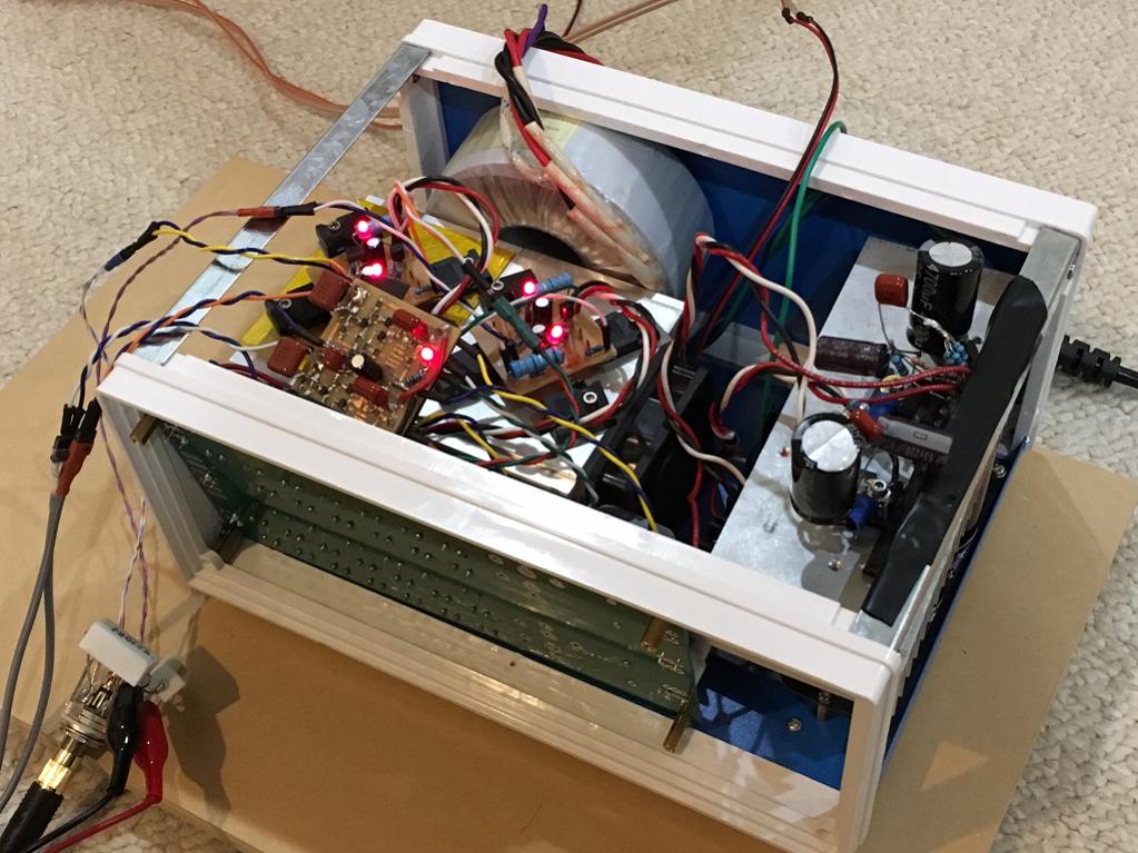
vs the 2 JFET amp's SMPS brick:
Not a fair comparison if you look at the supporting PSU for the big amp:
vs the 2 JFET amp's SMPS brick:
Last edited:
Ok, I connected the little amp to the big power supply with cap Mx and LC cap bank. It is reading 22.5v and bias current is now 130mA. The 2w resistors are probably running too hot as I can smell something funny so I put a fan on it. 1.7w is a bit close to rating of 2w.
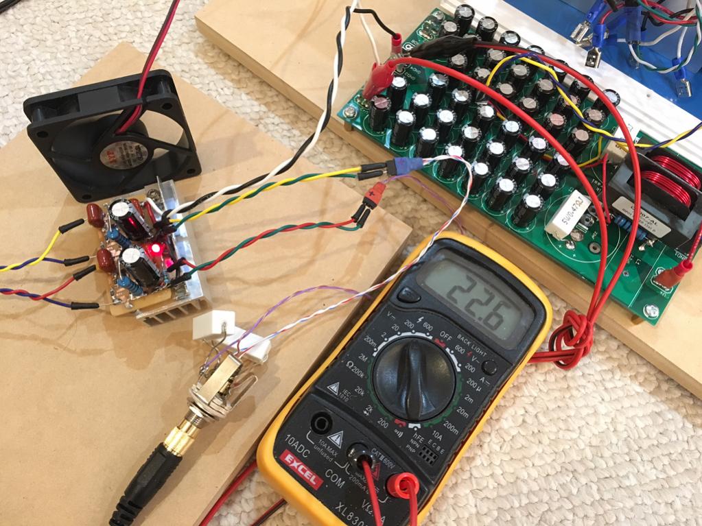
The sound is more transparent with ability to resolve very low level details. The bass has indeed improved quite a bit. I think overall it sounds pretty amazing now. Will need to listen more to see if it equals the big amp.
It's sounding very very nice with a good cap Mx and low ESR cap bank for a PSU. The increased voltage may have something to do with it as well.
I just put the Deep House dance mix on and getting some real deep bass with superb authority. Amazing sound coming from this tiny two transistor amp! Very very cool.
I will have to make dedicated cap Mx and low ESR cap bank for this guy. They make a huge difference.
So far so good. This is an excellent sounding, highly transparent and resolving amp with tremendous bass impact, Don't let it's diminutive size fool you, it is a serious head amp that can compete with some of the best. The harmonic distortion profile is superb. At 0.014% THD, it may not be in the ultra low range that some amps can claim. However, those amps rarely have just H2 and almost not H3 and nothing higher.
Highly recommended build!
Schematic as drawn is now tested and shown to sound good to my ears. I think you will like it too. Do yourself a favor and make a cap multiplier for it and add a cap bank with about 20 x 1000uF caps. The cap Mx is almost mandatory if using a trafo to prevent hum as this amp probably has poor PSRR.
three 6v lead acid batteries would also work very well.
Attachments

Last edited:
Happy New Year everyone!! 
Is eBay more or less the place to go for these Lovelytech OPS transistors, were you X able to measure yours, gm, pinch-off V, capacitance etc.? I feel tempted to throw in an order but a bit wary as I have been burned before buying through eBay from the "World Factory", also my economy isn't very good either so my few €$£ would preferably not be wasted on the lucky wheel.
Is eBay more or less the place to go for these Lovelytech OPS transistors, were you X able to measure yours, gm, pinch-off V, capacitance etc.? I feel tempted to throw in an order but a bit wary as I have been burned before buying through eBay from the "World Factory", also my economy isn't very good either so my few €$£ would preferably not be wasted on the lucky wheel.
I have not set up a rig to measure gm or pinch off v yet. I can measure Idss easily. I have an order placed for that handy dandy transistor MOSFET/FET tester and will test when it gets in. Although I am tempted to make this rig and try for myself it's just a matter of priorities in my time available.
The eBay link I posted seems to work - whether they are genuine I don't know. The seller says they are original. I think there was a source that was mentioned in another thread where you can buy matched sets for $6/pair. Deep Surplus or something like that.
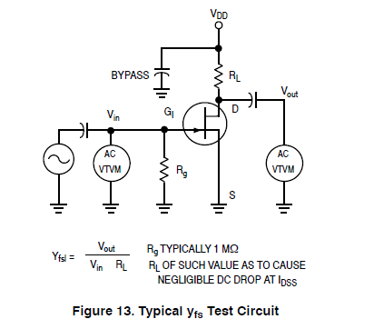
Also, from the Borbely article that Juma pointed out, in Fig. 5 of the first one looks like a pretty simple testing system:
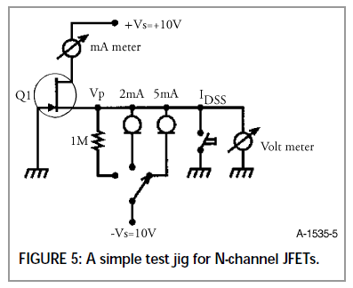
I will see if I can sneak some time out of my day to try this. It's made easier with a solderless breadboard and 3-pin screw terminals for installing the JFET. I currently am lacking a good lab grade PSU so may just use a 9v battery.
$6 for 4 JFETs was worth the risk for me to try it - and given that the amp makes music quite splendidly, I would hunch a guess these are the genuine article.
The eBay link I posted seems to work - whether they are genuine I don't know. The seller says they are original. I think there was a source that was mentioned in another thread where you can buy matched sets for $6/pair. Deep Surplus or something like that.
Also, from the Borbely article that Juma pointed out, in Fig. 5 of the first one looks like a pretty simple testing system:
I will see if I can sneak some time out of my day to try this. It's made easier with a solderless breadboard and 3-pin screw terminals for installing the JFET. I currently am lacking a good lab grade PSU so may just use a 9v battery.
$6 for 4 JFETs was worth the risk for me to try it - and given that the amp makes music quite splendidly, I would hunch a guess these are the genuine article.
Attachments
Last edited:
Oh, thanks for the link. These are genuine from the reports I have heard. Certainly, buy from here if you want to save yourself some aggravation. These are excellent prices given they have been sorted into Vgs already. I will link this in Post 1 for those interested in making this amp.
Thanks I will look into it as an option, and thanks also X for the test jig thingy info.
Now that we can select LU1014D with a 0,01 V increment between 0.62 - 1.22 Vgs, what would be a suitable Vgs value to pick, maybe Hugh can chime in on this.
Now that we can select LU1014D with a 0,01 V increment between 0.62 - 1.22 Vgs, what would be a suitable Vgs value to pick, maybe Hugh can chime in on this.
Thanks I will look into it as an option, and thanks also X for the test jig thingy info.
Now that we can select LU1014D with a 0,01 V increment between 0.62 - 1.22 Vgs, what would be a suitable Vgs value to pick, maybe Hugh can chime in on this.
Yes, Hugh will have to advise. I am just still figuring out the bias points between the gate and source that Hugh was discussing earlier. Vg-Vs at steady state operating point is a negative number. I wonder if that is the Vgs we should be looking for?
Best Vgs at 100ma Id is around -1.1V.
However XRK'S amp came at -1.8V at 120ma Id and his sonic testing seemed very good
Conclusion: Since these are tough to source any LU1014D would be fine because in self-bias source follower we are leveraging the high transconductance and tke low, 6.5 milliohm Rdson.
Thank you, X, a wonderful project with beautiful documentation and believable subjectives!
Hugh
Best Vgs at 100ma Id is around -1.1V.
However XRK'S amp came at -1.8V at 120ma Id and his sonic testing seemed very good
Conclusion: Since these are tough to source any LU1014D would be fine because in self-bias source follower we are leveraging the high transconductance and tke low, 6.5 milliohm Rdson.
Thank you, X, a wonderful project with beautiful documentation and believable subjectives!
Hugh
You are most welcome Hugh. Thank you for your guidance and inspiration, without which this would not have been possible.
Actual measured operating point is 9.43v gate and 11.30v source on channel 1 with 113mA bias using 22.3v supply voltage, for Vgs of -1.87v.
11.02v gate and 12.70v source for 127mA bias current on second channel, for Vgs of -1.68v.
These Vgs values are very close to the sim values - so I think the amp really may be working very close to predicted performance.
I hope that helps but shows the variability of unmatched JFETs. I don't hear a difference in volume between left and right channels though because it's a SE amp and the difference being driven is what makes the volume change. The input BF862's are matched for same Idss but not Vgs.
Btw, I just got a package of the small SMT MOSFETs in the mail today so if you feel like designing a variant of this using those, that would be great. I am still looking for a small portable amp that runs maybe 50mA bias. I am wondering if the depletion mode BSP MOSFET would be good for that. The ZXMN6A11ZTA is also a particularly attractive MOSFET at $0.60 ea.
- ZVN4306GTA (20v, 2.1A, 350pF, 330mOhm Rdson)
- ZXMN6A11ZTA (60v, 2.7A, 330pF, 120mOhm Rdson)
- BSP129H6327XTSA1 (240v, 350mA, 108pF, 6ohm Rdson)
Cheers,
X
p.s., I left it playing to burn in overnight and not sure if this is real, but it sounds even better today 🙂 I also have some nice namebrand 0.47uF 100v MKP (note the P) input caps and Panasonic OSCON 47uF 25v low ESR output caps I would like to try.
For today, I am so jazzed about this amp I want to throw together a quick cap Mx and small cap bank to see if coupled with a 24vdc SMPS, I can get similar performance to my penultimate trafo based home heater system in a much smaller and semi-portable format. I am also considering switching to 50R source resistors and adding a fan to heatsink for 200mA+ bias and see if the dynamics changes. Does 200mA bias in SE class A imply a max current swing of 100mA?
One more note... this experience has solidified something for me relative to quick amp building. Make the circuit board as small as possible and use SMT parts wherever possible. They are better quality I think and the tight layout should work better. Most of all, the smaller boards use less PCB raw material and less etchant. Finally, they make prototyping very fast because the layout is on top and you never flip the board back and forth. I am going to try to design my amps this way just because it is faster to make at home. This last amp was a miniscule 22mm x 22mm per channel. Even though there were only 2 actives - it proves to be very handy.
Last edited:
- Home
- Amplifiers
- Headphone Systems
- MOSFET Source Follower Headamp