Hey thats great news!!
I have listened to both the single and double OP1688 versions for a few hours this morning, and my objective listening is telling me that both versions are pretty much sounding or not sounding the same.
Using my assistant here I cant tell any real world differences..other than the positions of the volume pot needed for a particular level, they are both superlative to me.
I even went back to the V3, with no relay mute and its just as a good as the others.
To me an amp shouldnt add or take away anything from the signal. This amp design just does that. It justs acts as a nice clean amp...
So if your playing bitperfect source material and have a good dac the amp is just there doing what its intended to do....amplify!!!
Many people get caught up with "dirty" power from AC, USB cables etc...this DC amp doesnt have any of those perceived issues! Its simple and unique.
Great Job AGDR....
(now whats next??? )
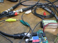
Oh, I forgot....I installed the led on the board in the back most position and put into one of the Altoids tin cases with the hole drilled out for it and even though its recessed the LED is very noticeable and shows up nicely!.
The longer knob for the volume pot seems to be the better choice as well in between the headphone jack and the audio 3.5mm input....
Alex
The longer knob for the volume pot seems to be the better choice as well in between the headphone jack and the audio 3.5mm input....
Alex
C-load testing: single and double stable with 2.2nF load! Part 3
Next up with the same purely-capacitive 2.2nF load with the double chip (parallel) amp now, verifying that is does oscillate, as it should with a large enough purely capacitive load.
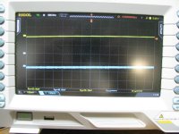
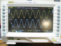
* 2.2nF, no resistance (resistor unclipped), parallel amp. Oscillation, as expected, but notice it isn't as bad as with the single chip amp in part 2 under the same test conditions, also as expected. I would expect the parallel double-chip amp to have more capacitive load drive, and that does appear to be the case.
* Next is the one I got a good laugh over. I replaced the 2.2nF capacitor in the test above with a 1nF and the Parallel Super CMOY is completely stable. That is driving nothing but a 1nF capacitor, no resistor. Pretty slick! 😀 On that 3rd plot I have run the scope time base way up and increased the sensitivity on the amp output channel to 100mV/div, looking for oscillation.
Finally I wanted to go back and do some THD+N tests with a capacitive load. I only used the 2.2nF here since we know it is stable with both the 16R and 150R from the previous tests here. I tested both the Parallel Super CMOY and the single Super CMOY. In summary, no significant change at all to THD+N by adding the 2.2nF across either the 16R o 150R loads on either amps!
I'm only showing the single chip amp here since the parallel was similar:
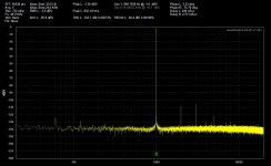
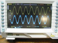
* 1KHz tone, 48Ksps rate, -10dBV, 16 ohm load. Again those 2nd and 3rd harmonics are largely the tester's (QA401) and not the amp.
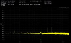
* 1KHz tone, 48Ksps rate, -10dBV, 16 ohm + 2.2nF load
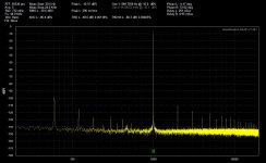
* 1KHz tone, 48Ksps rate, -1dBV, 150 ohm load
* 1KHz tone, 48Ksps rate, -1dBV, 150 ohm + 2.2nF load
I reduced the drive level for the 16R load to the -10dBV so it wouldn't over-run the output current capability of the single-chip CMOY.
Next up with the same purely-capacitive 2.2nF load with the double chip (parallel) amp now, verifying that is does oscillate, as it should with a large enough purely capacitive load.
* 2.2nF, no resistance (resistor unclipped), parallel amp. Oscillation, as expected, but notice it isn't as bad as with the single chip amp in part 2 under the same test conditions, also as expected. I would expect the parallel double-chip amp to have more capacitive load drive, and that does appear to be the case.
* Next is the one I got a good laugh over. I replaced the 2.2nF capacitor in the test above with a 1nF and the Parallel Super CMOY is completely stable. That is driving nothing but a 1nF capacitor, no resistor. Pretty slick! 😀 On that 3rd plot I have run the scope time base way up and increased the sensitivity on the amp output channel to 100mV/div, looking for oscillation.
Finally I wanted to go back and do some THD+N tests with a capacitive load. I only used the 2.2nF here since we know it is stable with both the 16R and 150R from the previous tests here. I tested both the Parallel Super CMOY and the single Super CMOY. In summary, no significant change at all to THD+N by adding the 2.2nF across either the 16R o 150R loads on either amps!
I'm only showing the single chip amp here since the parallel was similar:
* 1KHz tone, 48Ksps rate, -10dBV, 16 ohm load. Again those 2nd and 3rd harmonics are largely the tester's (QA401) and not the amp.
* 1KHz tone, 48Ksps rate, -10dBV, 16 ohm + 2.2nF load
* 1KHz tone, 48Ksps rate, -1dBV, 150 ohm load
* 1KHz tone, 48Ksps rate, -1dBV, 150 ohm + 2.2nF load
I reduced the drive level for the 16R load to the -10dBV so it wouldn't over-run the output current capability of the single-chip CMOY.
Attachments
-
 IMG_4386.JPG371.1 KB · Views: 458
 -
 1KHz 48Ksps -1dBV 150R + 2.2nF load.jpg145.7 KB · Views: 136
 -
 1KHz 48Ksps -1dBV 150R load.jpg145 KB · Views: 140
 -
 1KHz 48Ksps -10dBV 16R + 2.2nF load.jpg148 KB · Views: 137
 -
 1KHz 48Ksps -10dBV 16R load.jpg148.1 KB · Views: 138
 -
 IMG_4390.JPG205.6 KB · Views: 421
 -
 IMG_4389.JPG230.4 KB · Views: 432
 -
 IMG_4388.JPG385 KB · Views: 440
 -
 IMG_4387.JPG238.6 KB · Views: 448
Last edited:
Alex - thank you for the listening impressions!!🙂 I know that takes a lot of time A/B-ing with different music and the different amps.
What you've concluded there is what I would expect, that the parallel version should sound no better or worse than the single, unless a person had headphones that needed the extra current output to avoid clipping. So folks building a Super CMOY can save themselves $4 in parts and the soldering effort of one chip by just getting the single chip Super CMOY, unless musical peaks on a particular headphone in the collection will go over 75mA. I have SPL spreadsheets out at the project Google Drive link now for a number of different headphones, that show the voltage and current drive levels needed for different SPL levels.
On the other hand all this testing shows that the parallel Super CMOY doesn't seem to subtract anything, if someone prefers a parallel double chip CMOY.
Hey very intesting about the LED! I hadn't actually tried that mechanically yet, making the small hole for the light to escape with the LED in the back postion. That is great news that it works!
Last edited:
I spent this morning comparing the super 2 chip Cmoy to my Bottlehead Crack with Speedball mod...
It pains me to say that they are so close but yet different. Spending over $350 of a Crack with the Speedball mod you would want this amp to sound or be so much better than a battery powered solid state amp like the little cmoy!
But unlike most I try to be as objective as I can when comparing stuff...and in this case I would be happy with either amp. Depending on the music and my mood, they both do a marvelous job of making things sound good.
My subjective brain is telling me that the Cmoy is "clearer, cleaner, more articulate, crisper, more accurate due to less distortion?
You dont need to spend $350+ for a tube amp to have a great listening experience. Unless you really want to go the tube route and the nostalgia and worts that path presents. To me is was a walk back unto my past, growing up with vacuum tubes. A good, well designed tube circuit can play very well.
Its a great statement that the Cmoy does as well as it does and a wee bit better IMHO for a whole lot less dollars spent.
The things I think I heard that would dileniate them is the bass in the crack is just a bit loose compared to the Super Cmoy...The drum whacks and bass guitar is just as perfect as one can get...its that good. Again with levels matched and bitperfect well recorded source material it is no slouch.
The other thing to think about is that with the Crack OTL design low impedance headphones dont work that well....but the Super Cmoy does that well in spades!
Alex
Alex - thank you very much for the review!
I'm really glad you did the comparison vs. your tube amp, given that the OPA1688 is FET-input. The Crack has a very good reputation. I would say that is great news the Super CMOY may be in the same audible ballpark. 🙂
Good point about the OTL tube output circuit!
I'm really glad you did the comparison vs. your tube amp, given that the OPA1688 is FET-input. The Crack has a very good reputation. I would say that is great news the Super CMOY may be in the same audible ballpark. 🙂
Good point about the OTL tube output circuit!
Parallel Super CMOY PC boards now available
I've just added the Parallel Super CMOY boards out at my agdr vendor forum posting, at cost-for diyaudio members. I wanted to wait until I had all the THD and load testing done just in case there were any surprises with that parallel design.
The dual-chip Parallel Super CMOY PC boards are $1.50 less than the single Super CMOY boards because they are the regular HASL finish and not gold (EING). Lol, I was just so sure there would be a layout error somewhere in the V1.0 that I didn't get the gold finish. But no errors. The gold finish or not really won't make any audible difference, gold just looks good and the solder might flow just a tiny bit better during assembly.
I've now modified most the project materials too out on the Google Drive link to include the Parallel Super CMOY. The BOM is done, I still need to update the build instructions though. The Parallel version schematic and layout are in separate sub-folders there now under schematic and layout.
Build instructions updated to include the dual-chip Parallel Super CMOY version
I've just posted an updated build instruction document out on the project Google Drive link that includes the new Parallel Super CMOY dual-chip version, along with the existing V4.0 & V4.1 single-chip versions.
Congratulations to Alex on taking on the challenge of building his Parallel Super CMOY up from just the schematic, with no build instructions available yet! In fact, I don't think I had the combined BOM finished yet then either. A true DIY effort! 😀
I think that I've covered all the bases now, but if anyone spots anything I've left out in the build instructions, or anything that could be written more clearly, please post or PM.
While editing the build instructions I realized that the new Parallel version with the two OPA1688 chips has the same output current drive ability now as NwAvGuy's O2 headphone amp! The O2 has 140mA per channel with the two paralleled NJM4556A chips. The Parallel Super CMOY has 150mA with the two paralleled OPA1688s. 140mA was the spec that NwAvGuy gave, but I can say from first-hand testing the NJM4556A will do a bit more than that at low-THD, 150mA total is probably closer to the mark. So the O2 and Parallel Super CMOY really do have the same output current drive!
The NwAvGuy O2 headamp and the Parallel Super CMOY both use 1 ohm output balancing resistors, but the "Intersil" op-amp paralleling method here puts those inside the feedback loop of the first OPA1688. That means (nearly) zero ohms output impedance (still, the single-chip version is zero ohms) for the Parallel Super CMOY vs. 0.5 ohms for the O2. Which makes those capacitive load tests in the posts above even more amazing. The 2.2nF + 16R/150R is being driven with no series resistance at all on the Super CMOY output.
Another benefit of the Parallel Super CMOY occurred to me too. It spreads the chip power dissipation out among the two OPA1688 chips. So for anyone whose headphones will require higher voltage swings, near the maximum allowable with the OPA1688 chip and the given power rails here, going with the dual-chip Parallel version might give you longer chip life down the road.
Last edited:
Hello,
I was thinking about building one of these units after seeing Alex's positive reviews. I was wondering whether the two chip version would go through batteries any faster than the one chip version. Also, would there be any hiss on sensitive iems?
I was thinking about building one of these units after seeing Alex's positive reviews. I was wondering whether the two chip version would go through batteries any faster than the one chip version. Also, would there be any hiss on sensitive iems?
I was wondering whether the two chip version would go through batteries any faster than the one chip version. Also, would there be any hiss on sensitive iems?
Good question! I had forgotten to say anything about the current draw of the second chip. Extremely low idle current draw is another big plus about the OPA1688. Just 1.6mA idle current, max 1.8mA, from the datasheet. The second OPA1688 chip will slightly shorten the battery life, but it won't be any significant amount.
The LED string in the solid state relay for the power management circuit in the Super CMOY pulls 3mA total when they are "on" and the headphone relay coil draws 4mA. So adding it all up, the SSRs, the relay, and two OPA1688 chips the total idle current draw in the Super CMOY clocks in at around 10.2mA. Well that is the idle current draw of just one of the NJM4556A output chips in the NwAvGuy O2 headphone amp! Add in the second NJM4556A, 5mA for the NJM2068 gain chip and 1mA for NJM2903 comparator the O2 headamp eats 26mA at idle. The batteries are going to last a lot longer in the Super CMOY than in the O2 headphone amp.
Assuming your headphones are using somewhere around 3mA per channel on average (the AKG701, just picking an example at random, at 90dB SPL from the SPL charts at the project Google drive link) the total Super CMOY battery draw with the headphone load and the 10.2mA quiescent current would be 16mA. If you were using the Powerex 300mAh NiMH rechargeable "9V" batteries that would result in 300/16 = 18 hours of continuous run time. If you were using the 600mAh lithium batteries through you would get twice that, 36 hours! At 8 hours a day that would be 4 full days.
I haven't heard any background hiss at all on anything I've tried the amp with. I believe that Alex posted once he hasn't heard any either. But your ears may be better/younger than mine! 🙂
Last edited:
Absolutely no hiss of any kind that I can hear with the volume pot turned all the way up! Dead silent. I dont use any earbuds, just headphones from about 50 ohms to 250 ohms.
I would also say that all three versions of the AGDR Super Cmoy have worked first time..the only hard thing is soldering the TPS 3701 and the small capacitor on the little pc board....the 1688's are small as well but with the tape method of soldering its not that bad. If you can solder well you will be able to complete this amp fairly easily.
The Altoids tin requires some slow, methodical work, locating and drilling out the holes for the volume pot and two 3.5mm jacks.
Alex
I have tested with AKG K240mkii (55ohms) without any background noise(hiss), is perfect! But with Koss PortaPro (60ohms) it is present , nothing extreme, but it is quite noticeable. Can explain me why this happens?
I have tested with AKG K240mkii (55ohms) without any background noise(hiss), is perfect! But with Koss PortaPro (60ohms) it is present , nothing extreme, but it is quite noticeable. Can explain me why this happens?
Are you using the same circuit values as in the Super CMOY, with 825 ohm feedback resistors and the 10K volume pot? Higher resistor values can introduce noise.
Also make sure your inputs are grounded during your test. The Super CMOY, like NwAvGuy's O2 headamp, automatically grounds the inputs when nothing is plugged in. If the inputs are left floating you will hear noise on high gain.
I've attached spreadsheets for the Porta Pro at 90dB and 110dB. Those are very sensitive headphones! Just 69mV(rms) is all it takes to hit 90dB, while 690mV = 0.69Vrms hits 110dB. Headphone that sensitive will be more likely to show up any noise in an amp.
Attachments
How to wire the Super CMOY to an external output jack
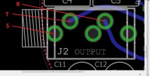
A question has come up about wiring an external 1/4" jack with the Super CMOY. I've created a diagram below that shows which holes the jack wiring connects to.
The "S", sleeve is the bottom part of the 1/4" plug. If you jack doesn't have an S marked ont he jack's terminals it is the jack connection that goes to that lower part of the inserted plug.
The "R", ring, is the band in the middle of the 1/4 plug, so the contact on your jack that mates up with that ring.
And the "T", tip, is the tip of the phone plug, the jack contact that mates up with that.
The extra 2 holes on the board under the output jack are not used. Those are switches which *are* used in the input jack to ground the contacts. Just to simpify the BOM (and prevent part mix-ups!) I used the same jack for output as for input.
Attachments
Last edited:
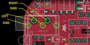
External input RCA jack wiring
Here is the companion diagram on how to wire up external RCA jacks for the input. The third hole in the middle towards the back of the input jack isn't used here, that is just another ground.
Keep in mind that with RCA jacks they won't automatically ground with nothing plugged in, so you might hear some hiss if turned all the way up with the inputs unconnected (as with any amp). The equivalent thing to use if you want to check background noise with the inputs grounded is RCA shorting plugs on both inputs.
Attachments
How to adjust the offset with the amp?
I am delighted with the sound! Nice work and thanks for help! 😀
But, there was little doubt I in relation to the offset.
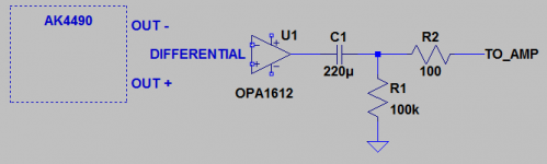
The signal is output from the converter with offset 2.5v.
In the amp, the capacitor C3 / C4 is already there to block DC then as it should be at the converter output? My image is correct way of thinking? Or is it not necessary? I have seen some cases where we used two capacitors on the inputs of the op amp, can explain me what better way?
I am delighted with the sound! Nice work and thanks for help! 😀
But, there was little doubt I in relation to the offset.
The signal is output from the converter with offset 2.5v.
In the amp, the capacitor C3 / C4 is already there to block DC then as it should be at the converter output? My image is correct way of thinking? Or is it not necessary? I have seen some cases where we used two capacitors on the inputs of the op amp, can explain me what better way?
Attachments
I am delighted with the sound! Nice work and thanks for help! 😀
Thank you for the listening impression! 🙂
The one set of DC blocking capacitors in the Super CMOY, the C3 & C4, is all you need. The DAC output will probably idle at 2.5Vdc due to 5V single rail power supplies. Setting the DC bias point at 2.5V allows the signal to swing a full volt or more in each direction above and below 2.5Vdc.
If you were sending that signal to an amplifier that did not have DC blocking capacitors already then you would need to add something similar to your diagram to move the output signal zero crossing from 2.5Vdc to 0Vdc.
But in the case of the Super CMOY you can apply the 2.5Vdc DAC "idle" output to the 10K pot in the CMOY and it will only draw 2.5V/10K = 250 microamps, which should be well within the output current capability of the DAC. The power dissipation in the pot will be 2.5^2/10K = 625 microwatts (0.625 milliwatts), again well below the 25 milliwatt rating of the pot. DC current going through the pot itself doesn't matter as long as the power dissipation (and therefore heating of the pot) is well below the maximum rating like this.
What will matter is any DC current through the pot wiper, which can cause scratchy sounds when turning the pot and wear down the pot resistive element faster, but that is blocked by the 3.3uF film coupling capacitors.
Also, as far as having capacitors in both places (output of the DAC and C3/C4 in the Super CMOY) that is OK, and probably necessary vs. just the 220uF. The problem here is that while the 220uF capacitor (in your diagram) would block the 2.5Vdc, a capacitor that large would probably be an electrolytic and would leak DC current to some extent. Especially when the amplifier is first started, electros will leak signficantly more current for the first 2 minutes than after the internal barrier has formed (the datasheets usually have a formula for it). If C3 and C4 were not there in the Super CMOY that "startup leakage current" of the 220uF electrolytic would make its way through the pot, and in turn through the pot wiper. The type of coupling capacitor in the Super CMOY (film) doesn't leak current like that on startup and leaks orders of magnitude less in steady-state.
Last edited:
OPA1688's in an O2?
Has anybody here tried OPA1688's in a vanilla NwAvGuy 02? I mean removing the 2 ea NJM4556 and replacing with 2 ea OPA1688 on adapter boards? Just curious if anybody has thought of this or tried it yet?
Has anybody here tried OPA1688's in a vanilla NwAvGuy 02? I mean removing the 2 ea NJM4556 and replacing with 2 ea OPA1688 on adapter boards? Just curious if anybody has thought of this or tried it yet?
Has anybody here tried OPA1688's in a vanilla NwAvGuy 02? I mean removing the 2 ea NJM4556 and replacing with 2 ea OPA1688 on adapter boards? Just curious if anybody has thought of this or tried it yet?
I've pondered that before! The big problem could be stability. NwAvGuy just has the typical output connected to inverting input for the voltage follower. To make the OPA1688 stable with large(r) capacitive loads (headphones and cables) johnc124 said he added that 47pF compensation capacitor in the datasheet, but that was for gains >1 it turned out. He ran the math for 1x gain a few posts back in the thread and that came up with 25 degrees of phase margin, he wrote. So he suggested a feedback arrangement that I'm using on the Super CMOY for 1x gain, the 825R resistor from output to inverting input, then another 825R in series with 1nF between the OPA1688 inputs. He says that should bump the phase margin up to around 50 degrees.
So long story short, it may take more parts than just the simple output-to-inverting_input short NwAvGuy has on each NJM4556A to make them stable. But hey might as well give it try! 😀 Headphones and/or cables that are not a big capacitive load might do OK. Just solder a couple of OPA1688's up on SOIC-8 to DIP-8 adaptors. Several huge benefits of the OPA1688 vs. NJM4556A for (paralleled) output chips:
* FET input and low input DC offset for much lower DC output offset than the 4556A.
* Vastly lower idle (quiescent) current than the 4556A. That leaves more (SOIC-8) package dissipation available for the signal dissipation.
* lower input impedance distortion at mid-pot then the NJM4556A
* Same 75mA per half-chip as the NJM4556A
* Same short circuit protection as the NJM4556A
* Slightly higher GBP and around 2.5x the slew of the NJM4556A. That 4556A slew of 3V/uS is the limiting factor in the O2 - the NJM2068 has twice the slew at 6V/uS. With OPA1688's installed that 6V/uS would become the new limiting factor
* Actually has slightly lower voltage noise, even though the 1688 is FET and the 455A is bipolar (input).
* Probably better THD+N, but I'm having some trouble doing an apples-to-apples there on the datasheet graphs and conditions
* Better CMRR and PSRR
If someone were really tricky with their layout it may be possible to get the two 825R resistors and 1nF cap soldered on the bottom of a custom SOIC-8 to DIP-8 adaptor board, if 0603 size or less were used. But the output-to-inverting_input traces on the O2 board would have to be cut - all 4 of them.
The thought has gone through my head of whipping up a new version of an O2 with the OPA1688's, but I've decided my O2 Booster Board is a better solution. 🙂 Uses NwAvGuy's original board and achieves all (except same total quiescent current as the 4556A) the benefits in the OPA1688 list above with OPA827's wrapped around LME49600. With even lower DC output offset (like 15uV!) and higher peak current, the 250mA per channel of the LME49600s, all with no paralleling required. The O2's 1R output resistors can be shorted straight across for true zero-ohm output. The OPA1688s would still require the balancing resistors since they are paralleled. Plus a headphone output relay there would be no room for on the O2's single board size. The Super CMOY essentially wound up being the new OPA1688 headamp rather than a new O2 version. 🙂
Last edited:
- Home
- Amplifiers
- Headphone Systems
- OPA1688 Super CMOY, 2x 9V with real ground and headphone relay - PCBs