@agdr
Do you ship pcboard to Canada?
Please PM me.
I already made a couple of project kits from JDS including their CmoyBB, I am interested in making this version of yours.
TIA
Do you ship pcboard to Canada?
Please PM me.
I already made a couple of project kits from JDS including their CmoyBB, I am interested in making this version of yours.
TIA
@agdr
Do you ship pcboard to Canada?
Please PM me.
I already made a couple of project kits from JDS including their CmoyBB, I am interested in making this version of yours.
TIA
Hi, you can get hold of me via email, the details are at the top of my vendor threaad here:
http://www.diyaudio.com/forums/vendors-bazaar/293309-agdr-audio-sales-thread.html
I'm have PMs turned off for a few weeks just due to not being able to log in much on the weekdays, didn't want anyone to not get a reply for a long time. I'll be checking email more often.
Yeah if you have made one of the "conventional" CMOYs the Super CMOY would be an interesting one to build. 🙂 There is a single chip and dual (parallel) chip with twice the output current per channel, but my advice is that unless you have some (probably older) headphones that are low impedance AND low sensitivity, the 75mA per channel on the single-chip OPA1688 is more than enough. There are some small downsides with the dual chip from slightly increased DC output offset and slightly increased noise floor (although still in-audible, at least to me), plus a small amount of additional battery drain from the second chip. So the single chip is best unless you really do require more than 75mA per channel, which would be relatively rare.
The dual chip version has the additioonal benefit of spreading heat dissipation over the two chips. So the other situation where it is useful is if you have headphones or IEMs in the, say, 50mA to 75mA range, but with a sensitivity level that would require most of the output voltage swing, like 3 to 4Vrms. Those parameters result in more chip dissipation. Using the dual chip version would spread the dissipaton out and may lead to longer chip life down the road.
I'm going to post a bunch of spreadsheets for various headphones out at the project Google Drive link in the first post in this thread. Those show the rms voltage and rms current requirements for the various headphones needed to hit 90dB Sound Pressure Level (SPL) and 110dB SPL. For modern headphones (which are usually high sensitivity these days), even at 110dB SPL, the voltage requirment is often under 2Vrms. Even with lithium "9V" cells (nominal 7.4Vdc, cutoff 6.4Vdc) you would get around 4Vrms output swing before battery cutoff with the OPA1688 chip.
I just continue to be extremely impressed with the OPA1688 chip! TI really has a winner there, IMHO.
Last edited:
Pot your battery leads for longer life
One potential long-term problem with the Super CMOY is the battery wires breaking off where they solder into the board, if the battery snaps get lots of flexing over time. Ideally I would have liked to find a connector that supports the wire insulation on the battery snaps.
The connection pins that mixih came up with above are a great way to go. Another is to simply "pot" the ends of the battery wires with hot glue on the top of the board, after they are soldered in. The blue should help support the wire insulation and reduce potential wire breakage.
One potential long-term problem with the Super CMOY is the battery wires breaking off where they solder into the board...
There are miles of wire in an average car/truck, and one broken connection can leave you stranded on the interstate. That's the primary reason there are no soldered connections in automotive wiring: the transition point (where the solder ends and the flex begins) forms a weak spot, just about guaranteed to break with even minimal flex (or vibration). Crimp-on connectors that anchor the wire are now the norm.
In small projects, I'm a huge fan of Molex KK connectors. These are crimp-style connectors that work very well in low-current applications:
KK® 254 Connector System - Molex
Their part numbering system can be a challenge, but worth the effort. For low-current application they are cheap, reliable, and you can crimp the pins to the wire with needle-nose pliers. I think they're too big to solve the flex problem inside a CMOY, but are good when space is not too restrictive.
In small projects, I'm a huge fan of Molex KK connectors. These are crimp-style connectors that work very well in low-current applications:
KK® 254 Connector System - Molex
Thank you for the pointer to those connectors! I'll get some and try them out. I can think of uses in some other projects. 🙂
I agree, that point where the tinned wire end stops is where wires always seem to break. Kind of defeats the purpose of highly stranded wire unless the wire insulation is supported too by the connector! Interesting about the car wire terminations! I had noticed they are almost always crimps but hadn't thought about why. Those crimps usually do have an upper part that goes around the wire insulation.
Last edited:
Headphone SPL charts now posted
I've moved all the headphone SPL charts to a top-level directory now on the Google Drive link (also have this link in the first post in this thread now):
https://drive.google.com/drive/folders/0B67cJELZW-i8eFVrX2taU25LUWs?usp=sharing
Each one shows the rms voltage and rms current a headphone amplifier has to supply to hit 90dB SPL and 110dB SPL for various headphones. There is the editable .xlsx file and an Adobe PDF for each.
The Super CMOY is good for around 4Vrms minimum output voltage swin on lithium rechargeable batteries (where the PM circuit cuts them off when dead) and around 5Vrms on throw-away batteries or NiMH rechargeables. The single-chip Super CMOY is good for 75mA per channel peak (53mA rms) and the dual 150mA per channel peak (106mA rms).
The third data block in the SPL spreadsheet, "how loud will an amp drive your headphones" isn't used in any of these published sheets, but you could use it if you enter the numbers above for the Super CMOY (for whichever battery type you are using).
Last edited:
Another birth
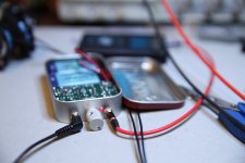
Another successful build. Birth certificates (snapshots) attached as proof.
Soldering on the comparator chip was a humbling experience. I thought I was fairly decent with an iron until I started that task. Thank goodness for a bench-mounted light/magnifying glass and solder wick. My geriatric eyes aren't what they useed to be.
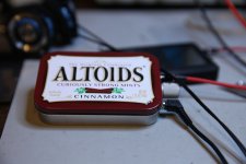
As you can see in the pics, I mounted the PCB upside down in the tin. Rather boring when opened, but doing so completely eliminated any interference between the lid and the phone jacks, knob, and LED. The lid closes tightly without objection, and looks good when closed.
The sound is, as expected, excellent. I like the OPA1688 very much. I've tried that chip in other projects, and have not been disappointed. I don't see how anybody could dislike these little wonders, but as always, YMMV.
Finally thanks to agdr. For the design, for publishing and maintaining the docs, and for making boards available. Thank you.
Another successful build. Birth certificates (snapshots) attached as proof.
Soldering on the comparator chip was a humbling experience. I thought I was fairly decent with an iron until I started that task. Thank goodness for a bench-mounted light/magnifying glass and solder wick. My geriatric eyes aren't what they useed to be.
As you can see in the pics, I mounted the PCB upside down in the tin. Rather boring when opened, but doing so completely eliminated any interference between the lid and the phone jacks, knob, and LED. The lid closes tightly without objection, and looks good when closed.
The sound is, as expected, excellent. I like the OPA1688 very much. I've tried that chip in other projects, and have not been disappointed. I don't see how anybody could dislike these little wonders, but as always, YMMV.
Finally thanks to agdr. For the design, for publishing and maintaining the docs, and for making boards available. Thank you.
Attachments
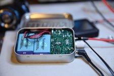
mlackey - looks fantastic! 🙂 Congratulations on your build. One suggestion I would make is to twist the battery leads.
You are right, the board mounts upside down on top of those 3.5mm jacks. I abandoned aesthetics for functionality on this one! Like you say it all works out just perfectly with no need to insulate the back of the board and plenty of clearance to the top of the can. I kind of enjoy coming up with weird mechanical solutions in my stuff, like the O2 Booster Board.
Yeah I've given up myself on soldering that TPS3701 chip! I had a bunch professionally soldered recently and I'm no longer going to supply just bare TPS3701 boards. That was my whole original goal with the adaptor board anyway, just to make the tiny TPS3701 bigger and convert it into a through-hole part. 🙂 As it turned out that adapter board also let me stack vertically a bit by putting it over the battery polarity protection diodes.
Last edited:
mlackey,
Great news on your build looks great the led light looks very nicely done!
Enjoy its a great headphone amp!
Alex
Great news on your build looks great the led light looks very nicely done!
Enjoy its a great headphone amp!
Alex
Finally
Afternoon,
Finally got around to building one of mine. Very nice, I use Player Pro on Android and have always struggled to get decent music reproduction straight from the phone even with their DSP pack.
Now its time to make a case for it.... I'll post some pics when I get to that point.
Question, I bought two... how well do you think the other would work as a pre-amp for a small 15W class D or am I just a noob chasing my tail?
Thanks,
KD
Question, I bought two... how well do you think the other would work as a pre-amp for a small 15W class D or am I just a noob chasing my tail?
Congratulations on your build! Yeah the phones just don't have the drive capability needed for some headphones and IEMs. Please do post the pictures when you get it in a can!
Yes definitely these could work as pre-amps. The OPA1688 chip is proving to be pretty versitile. Relatively low THD+N along with the high output current capability, lower than the class D amp. You can change out the two gain resistors to make the voltage gain anything you need. I have gain resistor values for everything up to 7x in the BOM now.
To make it AC powered consider that Mouser #919-RW-0509DDC-DC converter, makes +/-9V out of 5V (USB) input for $19. I bought one a few weeks ago to test but haven't had a chance to mess with it yet. I'll see if I can get it running and post some photos next week.
Very nice design. Could the SSR's be used on the headphone outputs? How long can a charged set of 9v LiPo's last playing 250ohm headphones?
Very nice design. Could the SSR's be used on the headphone outputs?
I actually tried that in V1.0! That first version had a place to solder on another small daughter board that either had an OPA1622 or another pair of SSRs on it. The board could be wired up to loop the OPA1688 around the OPA1622 (that was my original vision for the board) or the two additional SSRs could be used as a muting relay. That V1.0 didn't have the mechanical headphone relay. The output SSRs were AC-wired, while the battery SSRs are DC-wired (AC = both SSR mosfets in series, DC wired both in parallel).
I expected to see some crossover distortion with the output SSRs and sure enough, there was some, but it was surprisingly small. I still have the QA401 measurement photos here somewhere. Adding the low ESR after-battery-SSR power rail electrolytics (by the output jack) reduced the crossover even further (over having no electros at all) for reasons I still don't understand. This is crossover caused by the output SSRs, not the OPA1688.
But in the end it came down to money. The two SSRs wound up being more expensive than a mechanical relay and the SSR's internal LEDs pulled nearly the same current (3mA each SSR which were in series, 4mA relay coil) as the coil on the relay (the one being used now has a high sensitivity coil). And the mechanical relay has zero added distortion, of course. Also, rather interesting, I expected the SSR would switch a lot faster than the mechanical relay. Nope. One direction (off or on, can't remember) is about the same speed as the mechanical relay. At least that was the case for these SSRs with mosfets controlled by internal IR LEDs.
I did go with the SSRs for the battery control though due to the expectation that the on/off tracking (make/break synchronization) would be better with the SSR than with mechanical contacts, and that seems to be the case. For the power management circuit it is critical the two power rails turn on and off at exactly the same time to avoid thumps. That is one of the problems with the O2 headamp in the basic design, I have come to believe. I should say the existing DC-wired battery control SSRs don't introduce any distortion at all, I tested it with the QA401. I measured the output with the SSRs jumpered straight across and with them in circuit. Exactly the same result.
As for the second use of that early add-on board, the OPA1622, I couldn't solder it! About then I also came to realize the 75mA out per channel of the OPA1688 was completely adequate for most headphones. For the few headphones that needed more I could parallel them using the OPA1689, but since that wasn't a product yet I used two 1688's in the current dual version. As things turned out I prefer the two 1688s now. Better spreading of the power dissipation and routing is easier than the single quad chip.
Headphone sensitivity will figure in too to the current draw. I have SPL spreadsheets showing voltage swing and current requirements for a bunch of different headphones, at 90dB SPL and 110dB SPL, here:How long can a charged set of 9v LiPo's last playing 250ohm headphones?
https://drive.google.com/drive/folders/0B67cJELZW-i8eFVrX2taU25LUWs?usp=sharing
But in general a fellow wrote me recently that his single-chip Super CMOY, using the 600mAhr lithium polymer rechargeable cells (7.4V nominal) was going 6 days per charge with 4 or 5 hours a day usage. But again the sensitivity, impedandance, volume level, and even music (average levels) will all figure in, of course.
PM sent on your other question. 🙂 I don't think I've posted that yet, I've turned my PMs back on. Had some dental gum-graft surgery (ouch!!) that is finally over with.
Last edited:
Agdr,
I don't think I received any PM from you. So still wondering if PCBs are available for this amp and cost.
Thanks
Btw, not sure how SSR adds xo distortion as it stays on. Xo distortion happens in output transistors because of zero crossing (unless class A). If a MOSFET stays on fully throughout signal cycle it never goes through zero.
Agdr,
I don't think I received any PM from you. So still wondering if PCBs are available for this amp and cost.
Thanks
Btw, not sure how SSR adds xo distortion as it stays on. Xo distortion happens in output transistors because of zero crossing (unless class A). If a MOSFET stays on fully throughout signal cycle it never goes through zero.
Hi, just sent the PM. 🙂 With the "AC wired" SSR I think there is a handoff from one internal mosfet to the other at zero crossing - the two are in series.
Ok - I don't know the topology of what you are talking about but will take you word for it if there is a hand off then of course there is switching. But if you use it just like a relay - that is, as a switch that's not activated until a command signal is give to the "coil" or LED gate then it stays on. I know SSR with tens of amps capability are used in big power amps in SS forum very successfully with apparently no impact on sound. Certainly no xo distortion.
Here is thread:
http://www.diyaudio.com/forums/solid-state/264313-how-build-21st-century-protection-board.html
Here is thread:
http://www.diyaudio.com/forums/solid-state/264313-how-build-21st-century-protection-board.html
Ok - I don't know the topology of what you are talking about but will take you word for it if there is a hand off then of course there is switching.
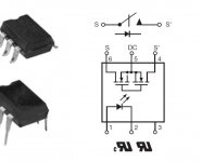
Good question! I've posted the diagram of the SSR wiring below. So the two mosfets are flipped with their drains connected together for "AC wiring". For "DC wiring" the two sources are also tied together to put the two internal mosfets in parallel. For AC wiring the signal goes in one source and out the other. For DC wiring the current path is through the common drain and out the common source. Since its an opto-mosfet SSR, there are no polarity concerns at the gates.
With discret mosfets I believe they dope the drain region much more heavily during fabrication than the source. So I think you can actually flip the source and drain, but the part won't be as efficient. There also might be a body diode formed in certain parts. I could be wrong about that though! There are likely a bunch of folks working in semiconductor fab on the forum, if anyone has some thoughts and insights here, please post. 🙂
Here is an interesting set of posts about swapping drain and source:
MOSFET drain / source difference
The amount of crossover distortion using the SSR for output muting was pretty small from my measurements, as I recall, most of it under -110dB and just one peak at -95dB. So yep that would probably work fine for a power amp and speakers. The headphone amps are probably held to bit lower THD numbers jsut given the proximity to the ears.
Another interesting thing that popped up in my testing was just how "off" the muting was, since it essentially forms a votlage divider between the "off" resistance of the SSR mosfets and the impedance of the headphone. It was good, but not vanishingly zero. There was a tiny amount of audio pass-through with 32R headphones, but the level was below the audible threshold. Again something that probably wouldn't matter at all with speakers, but might with some very sensitive headphones or IEMs.
Attachments
Last edited:
BOM update posted
I've just posted an updated Super CMOY BOM out on the project Google Drive link in the first post in this thread and attached below. The change is removing the line-item "pieces" of the tiny TPS3701 board and replacing it with a fully assembled and tested TPS3701 board. The pieces on there before were the bare TPS3701 board, the TPS3701 chip, a 0603 sized capacitor, and the connection pins.
The reason for the change is that chip is just too darn small for most folks to solder, me included! I had a bunch professionally soldered recently. A few folks had bought the bare TPS3701 boards and discovered they couldn't solder the chip and wound up having to get the assembled board. Plus that is the entire reason I made the TPS3701 adaptor board anyway, to make that tiny chip larger and convert it into a through-hole part for easy soldering.
Point of possible confusion: the TPS3701 chip is a tiny comparator used in the power management circuit. The main OPA1688 chip that goes on the Super CMOY board is also surface mount, but a lot bigger in the standard SOIC-8 size.
The BOM is consolidated now and applies to both the single-chip and dual-chip Super CMOYs. 🙂
Attachments
Last edited:
This will be a fun little amp to build. Looking forward to it. That's a lot of technology to squeeze into a third of an Altoids tin. Battery cutoff and headphone relay are nice features.
It really is a bunch of stuff in a small space! I was kind of impressed myself the way it turned out. 😀 Especially the trick of end-mounting the resistors on the dual board to make enough space for the 2nd chip. The boards make good use of the vertical space, I think, with those vertical 3.5mm jacks, the TPS3701 board sitting over the two battery polarity diodes. The trick of mounting it upside down in the tin on top of the 3.5mm jacks has worked out great too. I wonder if any other CMOY out there has done that? I haven't been able to find any in my searches so far.
- Home
- Amplifiers
- Headphone Systems
- OPA1688 Super CMOY, 2x 9V with real ground and headphone relay - PCBs