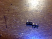
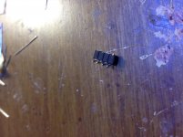
So while getting parts to build up a 2nd super cmoy(I broke the first one), I decided to look into the idea of a battery header. I haven't tested these in a board yet(still waiting on my pcb to arrive, USPS is holding it hostage), but I'm pretty sure they will work with one modification. The are MFG part # 929870-01-04-RA for the sockets and MFG part #929805-01-04-I for the header that go with them. You can see a picture of them in the first photo. The socket is only 5 mm high when placed in the pcb! The header is a little higher at 8.5 mm, but with a simple mod(bending the pins to right angles), they can be reduced to 6 or so mm. I'm thinking about soldering my battery wires to the header and shrink wrapping it to provide support.
Attachments

Hmm..that sound like a good idea to me! The battery connector isnt the greatest mechanical assembly. Let us know how it goes with some pix installed in the altoids tin can etc.
Ha!! USPS I hate it when stuff is dual shipped from UPS to USPS...I got a text msg this Tuesday stating my parts were delivered the previous day!!, They had not arrived. Spent hour on the phone with Amazon, UPS, and UPS, they opened and investigation!! As I was talking to them, the postman pulled up and delivered the mail, my parts arrived!!. Then later in the day I got a msg stating the parts were delivered today two hours earlier and an hour later I got another msg telling me my parts were delivered two hours later than the time of the first msg!! Ha!
Alex
:>)
The are MFG part # 929870-01-04-RA for the sockets and MFG part #929805-01-04-I for the header that go with them.
Good find! My original intent was to use a header and socket for the battery wires, but I couldn't find any short enough to fit. The maximum vertical space is the height of those 3.5mm jacks, around 12mm. The PCB holes are spaced 0.1" for a header. Looks like you may have found a "low profile" one that would work! Please post a photo when you get it wired up. 🙂
Ha!! USPS I hate it when stuff is dual shipped from UPS to USPS...
Isn't that something these days? Watching the tracking I see USPS handed off to FedEx, or DHL, or starting out with FexEx's wholesale postal then going to USPS.
"9V" battery internal resistance shootout: NiMH, lithium, primary - part 3
Continuing on from posts #59 and #60, internal resistance tests on a couple more types of "9V" batteries. 🙂
One is a 9V primary cell (non-rechargeable). I see these advertised a lot for "10 year life in smoke detectors". Right off the bat that says to me "low current capability".
The other is the "low self discharge" cousin to the standard Tenergy "9V" (8.4V nominal) NiMH rechargeable often used in the O2 headamp. This type will stay charged much longer on the shelf, unused, but I've also expected that to mean trouble in terms of current capability.
I tried using the same 160R resistor I used in the previous tests, but the voltage under load on either battery did not stabilize well and continued to drop. That implies the 60mA discharge rate is too great for the batteries, which matches up with what I was expecting. I switched to using a 470 ohm (meaures 475R) to drop the discharge rate to 20mA. Still continues to drop at 20mA, but the rate of drop is much less than at 60mA.
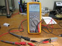
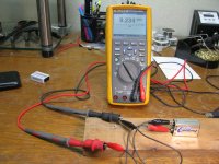
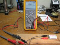
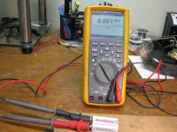
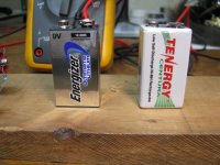
Photos:
* first two are the test setup, with the two batteries and 475R resistor
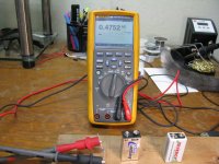
* Next two are the open circuit voltage (9.681Vdc) and load voltage (9.623Vdc) for the low self discharge NiMH. Going through the math in post #59 comes up with an internal resistance of 2.9 ohms.
* And the final two are open circuit voltage (9.234V) and load voltage (9.172Vdc) for the primary lithium 9V. This one comes up with an internal resistance of 3.2 ohms.
The lithium polymer rechargeable "9V" from the previous tests has both of these beat by a mile! There wasn't any rapid voltage drop even with the load of 60mA attached. No problems handling high load currents, plus the 0.4 ohm or so internal resistance.
Continuing on from posts #59 and #60, internal resistance tests on a couple more types of "9V" batteries. 🙂
One is a 9V primary cell (non-rechargeable). I see these advertised a lot for "10 year life in smoke detectors". Right off the bat that says to me "low current capability".
The other is the "low self discharge" cousin to the standard Tenergy "9V" (8.4V nominal) NiMH rechargeable often used in the O2 headamp. This type will stay charged much longer on the shelf, unused, but I've also expected that to mean trouble in terms of current capability.
I tried using the same 160R resistor I used in the previous tests, but the voltage under load on either battery did not stabilize well and continued to drop. That implies the 60mA discharge rate is too great for the batteries, which matches up with what I was expecting. I switched to using a 470 ohm (meaures 475R) to drop the discharge rate to 20mA. Still continues to drop at 20mA, but the rate of drop is much less than at 60mA.
Photos:
* first two are the test setup, with the two batteries and 475R resistor
* Next two are the open circuit voltage (9.681Vdc) and load voltage (9.623Vdc) for the low self discharge NiMH. Going through the math in post #59 comes up with an internal resistance of 2.9 ohms.
* And the final two are open circuit voltage (9.234V) and load voltage (9.172Vdc) for the primary lithium 9V. This one comes up with an internal resistance of 3.2 ohms.
The lithium polymer rechargeable "9V" from the previous tests has both of these beat by a mile! There wasn't any rapid voltage drop even with the load of 60mA attached. No problems handling high load currents, plus the 0.4 ohm or so internal resistance.
Attachments
Last edited:
Thanks AGDR. Received my Super Cmoy today and got it installed. Will attach pix and listening comments later.
Thanks AGDR. Received my Super Cmoy today and got it installed. Will attach pix and listening comments later.
Please do post some pictures! I'll be curious to hear your listening impressions.
Appologies if you tried to PM and it bounced. I'm going to be taking a little break from audio for the rest of the year due to some issues on my end. I've turned off PMs so folks wouldn't leave one and then not get a reply for a long time. 🙂 I'll check into the threads here though as time permits.
![20161029_145323[1].jpg](/community/data/attachments/527/527189-86447512bff8096edca72b53ab4b5e5a.jpg?hash=hkR1Er_4CW)
![20161029_145309[1].jpg](/community/data/attachments/527/527212-6df8c04f2789c8f00d6c6a0cf984b4f7.jpg?hash=bfjATyeJyP)
dwpeterson!
Welcome to the AGDR Super Cmoy club!! Thats a neat Altoids tin!! I hope you enjoy the amp, I have three of them and they are really great, I have done a lot of listening and comparing...will be great to hear your impressions!.
AGDR all the best on your end!
Alex
Welcome to the AGDR Super Cmoy club!! Thats a neat Altoids tin!! I hope you enjoy the amp, I have three of them and they are really great, I have done a lot of listening and comparing...will be great to hear your impressions!.
AGDR all the best on your end!
Alex
Here are the PIX, the listening results will have to wait until I upgrade firmware on my Yamaha RX-A1040 receiver.
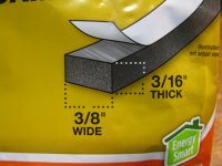
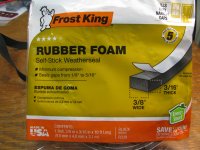
Looks great! 🙂 I've been putting a couple of strips of foam rubber weather stripping, from the big box home stores, under the lid over the battery area to take up the remaining space between the lid and the batteries. Works great. Photos below.
Here is an easy way to convert a Super CMOY to desktop use if anyone should be interested, Mouser #919-RW-0509D:
http://www.mouser.com/ProductDetail/RECOM/RW-0509D/?qs=dE2Iv29Bx0ExkVMuTy5Z8g%3d%3d
That is an isolated +/- 9Vdc & 167mA per rail output, DC-DC converter (4.5V to 9V input) that about 10mm smaller in each of the three dimensions than the size of one 9V battery. 🙂 Could be fed by regular USB 2.0 (500mA) thanks to the 73% efficiency, or USB 3.0 (1A). With the 167mA out on each rail it is enough to power either a single (75mA per channel) or double chip (150mA per channel) Super CMOY. The part is $18. Mouser has cheaper ($8) DC-DC converters that are 4.5V to 5.5V in and 111mA out, but they run at 45KHz. They are also SIPs that are about the same height as the 3.5mm jacks on the board. This one runs at 100KHz to 150KHz, out of the audio band, and is low profile DIP.
To DIY it just flip the convertor over and glue the top of the part to the bottom of the mint tin with RTV or hot glue. Extra credit: use a thermally conductive RTV if you can find one at a reasonable price, which will heat sink it to the mint tin. Then let the pins stick through some perfboard and point to point wire it. Cut off the battery snaps and solder those wires to the output pins of the converter. Then the power wires from a USB cable through a hole in the tin to the converter input, plus 499R load resistors (see below) across each converter output. 🙂
One trick: any of these DC-DC converters need a minimum of 10% load to maintain regulation. The Super CMOY only pulls about 16 microamps when off (the TPS3701 chip and voltage divider), so it would be necessary to put a 9V/18mA = 499 ohm load resistor on each converter output rail to bleed off the 10%. That is only 150mW, a 1/4 watt resistor is fine. I bumped the 10% up to 11% here (18mA) here to stay well within the range.
Alex - thanks! With any luck I'll be a happier camper mid- December. 🙂
Attachments
Last edited:
When you say "across" does that mean from each rail to ground via the 499Ohm resistor or in series?
Alex
:>)
Alex
:>)
When you say "across" does that mean from each rail to ground via the 499Ohm resistor or in series?
Alex
:>)
Good question! 🙂 One 499R from each rail to ground. It is just working as a load resistor to essentially "waste" 9V/499R of output current, providing that 10% minimum load the converter needs.
It would take some clever DIY work to get the USB cable attached! I assumed there was such a thing out there as a USB 2.0 cable with stripped, tinned, ends. Just did a search and nothing on eBay or anywhere else. Hmmm.... Maybe a micro-USB jack could be mounted on the perfboard, above the converter, then a (regular) USB - to - micro USB cable use. Then drill a larger hole in the side of the mint tin to allow the micro USB end to go through.
If I get some time next year maybe I can whip up a circuit board the converter and a micro-USB jack could solder too, with the hole for the micro USB on the other end of the mint tin from the CMOY controls.
I assumed there was such a thing out there as a USB 2.0 cable with stripped, tinned, ends.
Hello agdr,
Being an avid ebay fan, I just had to look there. I included "diy" in the search phrase, and that did turn up a couple items. Best wishes and hope all goes well for you.
2pcs USB Micro B Female Type DIY Connector Port Plug Jack Cable Replacement | eBay
Micro USB 5 Pin Female Jack 2 Pin 2 Wire Charge Cable Cord Connectors DIY 30cm | eBay
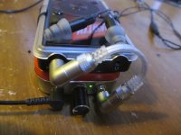
Alright, so I finally have the finished pics of my AGDR super Cmoy with detachable battery! Sounds great and everything works. I just used it on a long trip and I must say, it performed very well with my noise isolating(should I say noise killing?) er4 headphones.
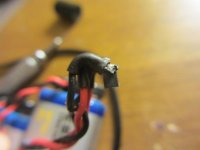
First pic is of the socket, I bent the pins so the cable would naturally move up and over thought he battery compartment.
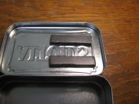
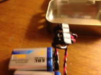
Second and third ones are of the battery assembly after having heat shrink applied as a insulator
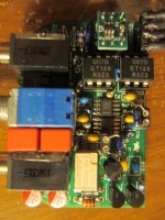
Fourth one is a board shot. I forgot to mention I made more mod: replaceable rain resistors. I used a cut up dip 20 socket because I has a few on hand.
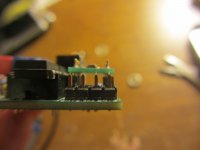
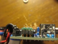
No. 5 and 6 are side shots that show clearance to the header. There still is a lot.
No7 shows the board fitting in a regular Altoids tin. Clearance are about the same as the original.
No 8 is a finished photo of is in my portable rig. Sounds great! Thanks AGDR for helping me debug!
P.S Do these photos allow me to join the AGDR Cmoy club.
First pic is of the socket, I bent the pins so the cable would naturally move up and over thought he battery compartment.
Second and third ones are of the battery assembly after having heat shrink applied as a insulator
Fourth one is a board shot. I forgot to mention I made more mod: replaceable rain resistors. I used a cut up dip 20 socket because I has a few on hand.
No. 5 and 6 are side shots that show clearance to the header. There still is a lot.
No7 shows the board fitting in a regular Altoids tin. Clearance are about the same as the original.
No 8 is a finished photo of is in my portable rig. Sounds great! Thanks AGDR for helping me debug!
P.S Do these photos allow me to join the AGDR Cmoy club.
Attachments
-
 IMG_2076.jpg533.4 KB · Views: 377
 -
 IMG_2080.jpg511.8 KB · Views: 371
 -
 IMG_2837_result.jpg513.3 KB · Views: 356
 -
 IMG_2826_result.jpg526.9 KB · Views: 363
 -
 IMG_2833_result.jpg514.5 KB · Views: 350
 -
 IMG_2832_result.jpg680.5 KB · Views: 173
 -
 IMG_2825_result.jpg490 KB · Views: 185
 -
 IMG_2846_result.jpg884.7 KB · Views: 189
Hello agdr,
Being an avid ebay fan, I just had to look there. I included "diy" in the search phrase, and that did turn up a couple items. Best wishes and hope all goes well for you.
Ah so they do exist! Thank you very much for those links. 🙂 When I pulled up the second one there was a listing for a female version too:
USB 2.0 A Type Male Plug 4 Pin 4 Wire Data Charge Cable Cord Connectors DIY 30cm | eBay
With that cable just solder the two power wires to the converter pins and away it goes!
Alright, so I finally have the finished pics of my AGDR super Cmoy with detachable battery!
Hey that is some very fine DIY work there! Thanks for sharing your photos. Those power pins and wiring came out really nice. I always figured there wouldn't be enough vertical room, but in your side shot there is a good 2mm or more there. I like that short 3.5mm source cable too. Fantastic idea on making the gain resistors replaceable, I do that with O2 amp builds. That would make trying different amp gains a snap. Definite member of the Super CMOY club!! 😀
How many days are you getting on those 600mAhr lithium batteries between recharges? I'm glad you twisted the battery wires together on each snap. That is something I've forgotten to add in the build instructions and in fact something I've been forgetting to do myself!
Last edited:
How many days are you getting on those 600mAhr lithium batteries between recharges?
Hmmm. I'm not really sure. They've already lasted through 2 mp3 player recharges, though those batteries weren't fully charged when I put them in. Based on that I'd estimate over 30 hours hours easily. My iems aren't very efficient judging from the SPL calculator so that may be a factor. Also, those batteries were cheapies, so I'm not sure if they're actually 600mah 😛. The 4 battery charger has a charging table that lists battery capacities and the number you can charge at once, which makes me worry it's a simple timer charger... not good.
Forgot to mention that my mp3 player lasts 10 hours or so, so that should factor into the calculations too. Any ideas on how to make the resistors easier to insert? Currently the leads tend to deform when I try. (I was motivated to add that battery header because the board is incredibly hard to desolder. I've had soldered battery cables break on me before.... That was good foresight designing it to accept headers!)
Also, my condolences on your situation, I hope it improves soon.
(gah, missed that edit window, real unforgiving to typos)
Also, my condolences on your situation, I hope it improves soon.
(gah, missed that edit window, real unforgiving to typos)
Based on that I'd estimate over 30 hours hours easily.
Hey pretty good at 30 hours! You are right about the battery capacities, they always lie. 🙂 600mAhr is almost certainly no more than 500, and 250mA (the regular O2 NiMH) are probably more like 200 or 220.
The IEM efficiency definitely figures into battery life.
The Super CMOY board is definitely a challenge to unsolder, at least without a vacuum desolderer. My Hakko 808 takes anything right out, but with solder wick the results probably won't be good. Years ago I used the "plunger" type vacuum desolders that don't cost very much and they would usually do the job after a few tries.
Those 1/8W leads are thin! You might try tinning it with some solder. just tap it with the hot iron after to get rid of any excess. I do that with the battery leads before putting them in the holes to solder. Keeps all the wire strands in place.
Yeah I've wound up with both some medical and business issues to deal with for the rest of the year, which are keeping me busy. 🙂
Good work on your build!
- Home
- Amplifiers
- Headphone Systems
- OPA1688 Super CMOY, 2x 9V with real ground and headphone relay - PCBs