Hi Tibi
I see on you web site that both SALIGNY standard and SALIGNY LC
"Require a minimum output capacitor of 1000uF".
I have a small soft start unit 9Vac, 1N4007 bridge, 470µF capacitor, current draw 90mA (I could increase capacitor and bleed resistor).
I guess that the diode switching noise is not a lot at such low current.
My question is :
There is a lower voltage limit (6Vac), but is there a lower current limit where an ideal bridge becomes overkill and unnecessary.
all the best rebone
Rebone,
1000uF should cover a wide range of applications up to 1Ampere.
To answer your question, it depends on application. There are low current applications, where Saligny can be a real benefit because of low noise. So there is no minimum current.
On other hand, I do not see the benefit of having Saligny in a soft start circuit.
Regards,
Tibi
Thank you, Gábor !
If the tubers are looking for such dual diode, to replace a double diode tube rectifier, than I may easily design one.
Write down your desired specs.
Regards,
Tibi
Are you planning another group buy later for this dual diode for center tapped tubers?
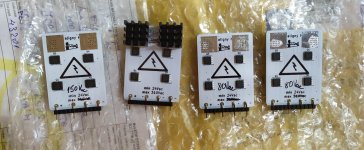
Hi Tibi, I received four HV bridges two days ago, my three bridges 320V, 80V and 80V are all right, but I got complaints from the bridge ordered by friend "Merlin el Mago" you remember, our orders are joined to my address to save delivery costs. His bridge is rated at a higher voltage (150V) than requested (125vac, O,8A, 50Hz). Please see pic atch. on left side. Is that all right within the specifications, or was misplaced, intended for another person?
Jordi
Jordi
Attachments
Are you planning another group buy later for this dual diode for center tapped tubers?
Few fellows have requested this to me. It seems that "tubers" like such type or rectification, so I'm designing such dual diode. I'm testing right now one with SIT transistors and is performing very good. I'll post on my twitter account few pictures soon. If there is enough interest a GB will follow.
Regards,
Tibi
Last edited by a moderator:
Bridges delivered, at last! It has been a long wait, considering the relatively short distance...
Today i tried the 2 lower voltage/higher current ones. They work like a charm with my center tap transformers. The rear metallic pads for heatsink are quite hot after half an hour of play, do you think i can fix them with thermal glue/thermal pads to some aluminium fins screwed to the metal base of the chassis?
Transformers ringing lowered a bit, but didn't disappear. Voltage got some higher. Sound seems slightly more natural, maybe with a touch more dynamics (due to the higher voltage?) but not smoother as i was expecting.
But it's just the first listening, more time is needed to tell the real difference.
Thank you Tibi for your work!
Thank you, Luca for your feedback !
If you want to attach a small heatsink on the regulators, here is what you need:
ICK BGA 14 X 14 X 10 FISCHER ELEKTRONIK - Radiator: extrudat | neagră; L: 14mm; W: 14mm; H: 10mm; aluminiu; ICKBGA14X14X10 | TME - Componente electronice
ART.AGT-116 AG TERMOPASTY - Adeziv termoconductor | albă; 10g; Termoglue; 1W/mK; max.200degC; TERMOGLUE-10 | TME - Componente electronice
I have used Hernon dissipator 746 for some time, but this is no longer easy to find.
Allow Saligny HVHF some burning time.
Regards,
Tibi
Thank you Tibi for your reply,
that's exactly the thermal glue i have, i would use that. But to be honest, it would be convenient for me to fix the bridges to the aluminium chassis fins (even if less effective as heat sinks) just to give them a stable still position in the chassis, as in my amp PS section i don't have a PCB to solder them and for the first try they're still "flying". Previous diodes where fixed to those aluminium fins indeed.
Just wanted to be sure connecting the rear metal pads to chassis "ground"won't be a problem. The rest of the bridge would not be connected, see picture below
Last edited:
- Home
- Group Buys
- Ideal Bridge second GB