Successful Test of Verification Build
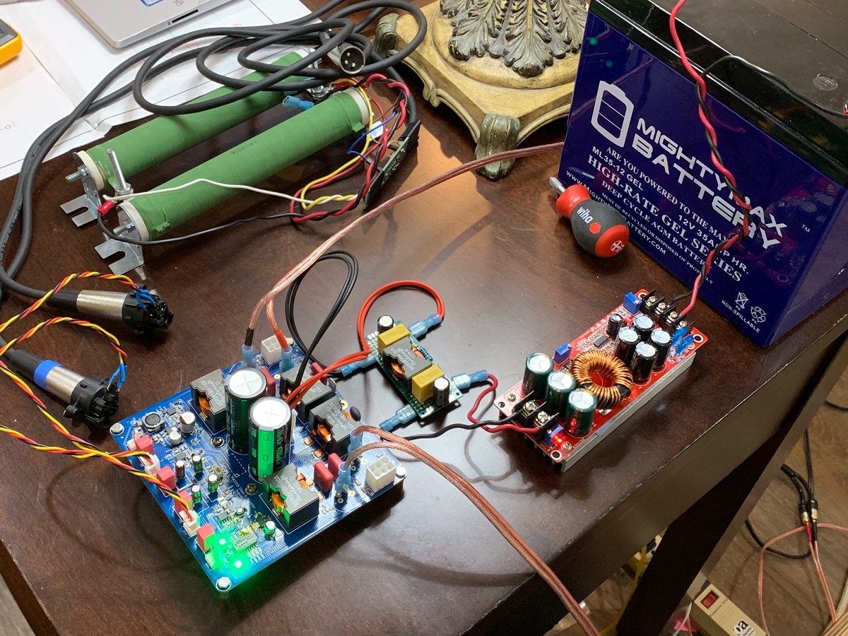
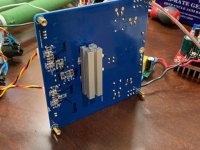
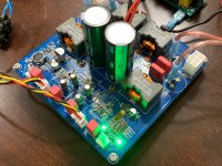
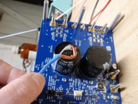
I made some proper balanced XLR to Molex connectors and that solved the bad balanced stereo BTL issue. However, afer about 20 seconds of play, the amp would show an error light and shutdown. Since there was a time delay, I thought to myself it might be the heat buildup from running without a heatsink. Even though this is Class D, I installed a makeshift heatsink using a Makerbeam 15mm aluminum channel and a small piece of copper Faston tab as the thermal spacer to raise the heatsink above the thickness of the nearby SMT components on the bottom side. It works beautifully now! Playing for about 20 minutes now with no errors or issues. That little heatsink is warm as I think the dissipation from this amp is quite high despite Class D. Probably at least 3W quiescent feeling the temp with my hand. They are connected to my 10F/RS225 FAST speakers. Absolutely silent with source off - very quiet amp. The music is playing and sounds great. I will post an updated schematic showing which solder jumper to connect and also which DIP switch settings to use for stereo BTL (the mode I assume most people will use). I will test the 4 channel SE mode at some point. That mode is supposed to sound even more hifi with lower distortion.
So a big hats off to JPS64 for making an amp that sings the first time around! It's not easy as this was kind of complicated with all the switches and options. Thank you, JPS64!!!


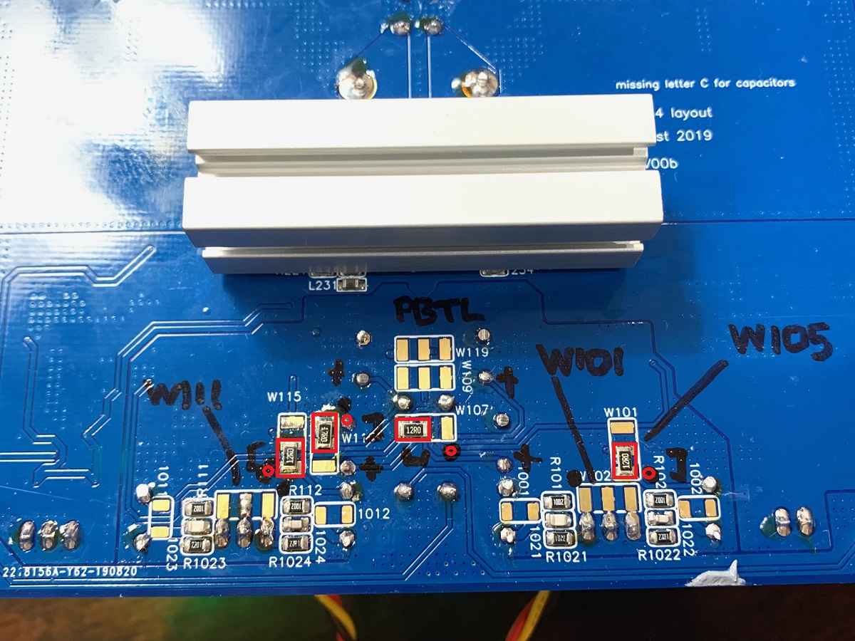
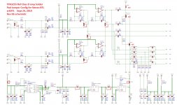
Edit: here is the schematic showing which Wxxx solder jumper pads need to be connected. For the opamp section, I used a low resistance 12ohm (any value from 0ohms to 50 ohms would be fine) 1210 resistors to make the connection. For the smaller power supply pads, they could simply be bridged with a dab of solder. The red lines show which way the solder pads need to be bridged.
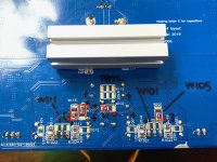
Photo closeup of jumper configs, red circles show pad number 1:
I made some proper balanced XLR to Molex connectors and that solved the bad balanced stereo BTL issue. However, afer about 20 seconds of play, the amp would show an error light and shutdown. Since there was a time delay, I thought to myself it might be the heat buildup from running without a heatsink. Even though this is Class D, I installed a makeshift heatsink using a Makerbeam 15mm aluminum channel and a small piece of copper Faston tab as the thermal spacer to raise the heatsink above the thickness of the nearby SMT components on the bottom side. It works beautifully now! Playing for about 20 minutes now with no errors or issues. That little heatsink is warm as I think the dissipation from this amp is quite high despite Class D. Probably at least 3W quiescent feeling the temp with my hand. They are connected to my 10F/RS225 FAST speakers. Absolutely silent with source off - very quiet amp. The music is playing and sounds great. I will post an updated schematic showing which solder jumper to connect and also which DIP switch settings to use for stereo BTL (the mode I assume most people will use). I will test the 4 channel SE mode at some point. That mode is supposed to sound even more hifi with lower distortion.
So a big hats off to JPS64 for making an amp that sings the first time around! It's not easy as this was kind of complicated with all the switches and options. Thank you, JPS64!!!
Edit: here is the schematic showing which Wxxx solder jumper pads need to be connected. For the opamp section, I used a low resistance 12ohm (any value from 0ohms to 50 ohms would be fine) 1210 resistors to make the connection. For the smaller power supply pads, they could simply be bridged with a dab of solder. The red lines show which way the solder pads need to be bridged.
Photo closeup of jumper configs, red circles show pad number 1:
Attachments
-
 TPA3255-Test-Success-01.jpg509.7 KB · Views: 1,823
 -
 TPA3255-Test-Heatsink-02.jpg406.6 KB · Views: 1,379
 -
 TPA3255-Test-Success-03.jpg491.2 KB · Views: 20,503
 -
 TPA3255-Solder-Pad-Jumpers-Config-Stereo-BTL-mode-v0b.jpg508.1 KB · Views: 339
 -
 TPA3255-Solder-Pad-Jumpers-Config-Stereo-BTL-mode-photo.jpg394.1 KB · Views: 2,318
Last edited:
For the "well engineered" character i'd suggest optimizing R138 for best performance like shown in http://www.ti.com/lit/ds/symlink/lm5010.pdf
Section 8.2.2.1.5
The value depends on several parameters. I'd tune for 25mVpp (which is stated minimum in DS)
The EVM isn't using it at all.
Section 8.2.2.1.5
The value depends on several parameters. I'd tune for 25mVpp (which is stated minimum in DS)
The EVM isn't using it at all.
However, afer about 20 seconds of play, the amp would show an error light and shutdown. Since there was a time delay, I thought to myself it might be the heat buildup from running without a heatsink. Even though this is Class D, I installed a makeshift heatsink using a Makerbeam 15mm aluminum channel and a small piece of copper Faston tab as the thermal spacer to raise the heatsink above the thickness of the nearby SMT components on the bottom side. It works beautifully now!
I think we can guess the efficiency of this TPA3255 class D amplifier chip at about 90 %. I don't know the supply voltage you're using, but at an total output power of, say, 100 watts the chip dissipates 11 watts after all. I do imagine that even at idling the chip's dissipation is too high to get rid of the heat without heatsinking.
Best regards!
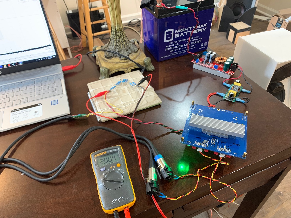
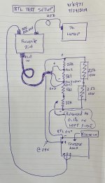
Some initial measurements using a metal thin film resistor load of 6.6ohms (8x 3.3ohm 2W MTF in series parallel + series) with a 22k+5k1+5k1+22k resistor divider with a 0v middle node for measurements of a BTL amp. Voltage between middle (0v node) and node btwn 5k1 and 22k fed to Focusrite XLR inpiut.
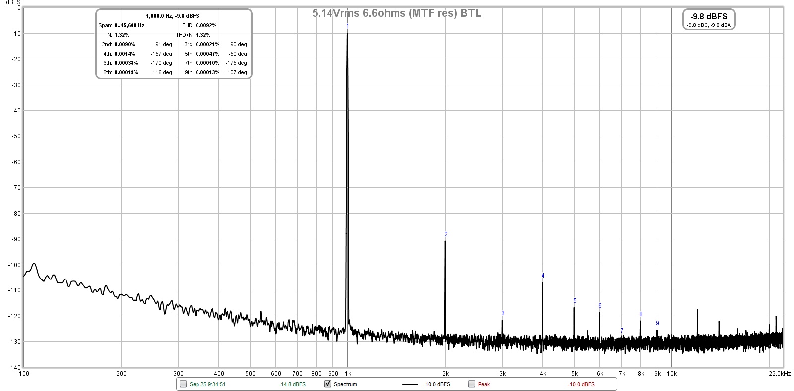
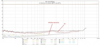
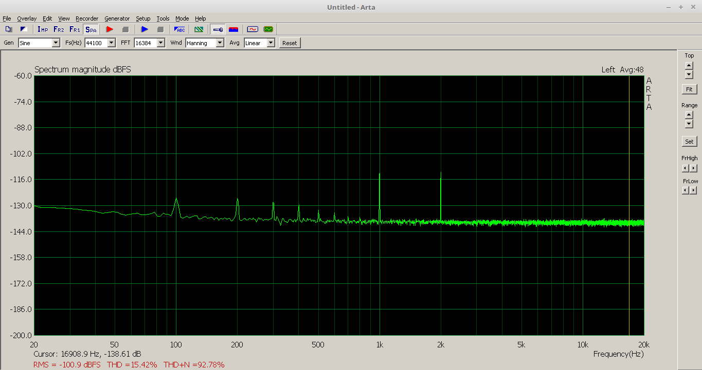
My limited size temporary heatsink only allows lower powers to be tested at present. The amp displays a nice 2nd harmomic dominant profile, as opposed to the 3E and EVM style layouts that exhibit 3rd order dominant harmonic distortion with alternating high/low odd order distortion. This amp exhibits alternating high/low EVEN order distortion. So I think for many people, this may sound better and less fatiguing. A sweep over frequency space shows that the H2 is dominant and quite a bit higher than the rest. Not sure where this is coming from, but for people with propensity for SE Class A amps, this will sound right at home.
Setup:
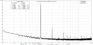
FFT for 5.14 Vrms into 6.6ohms (4W):
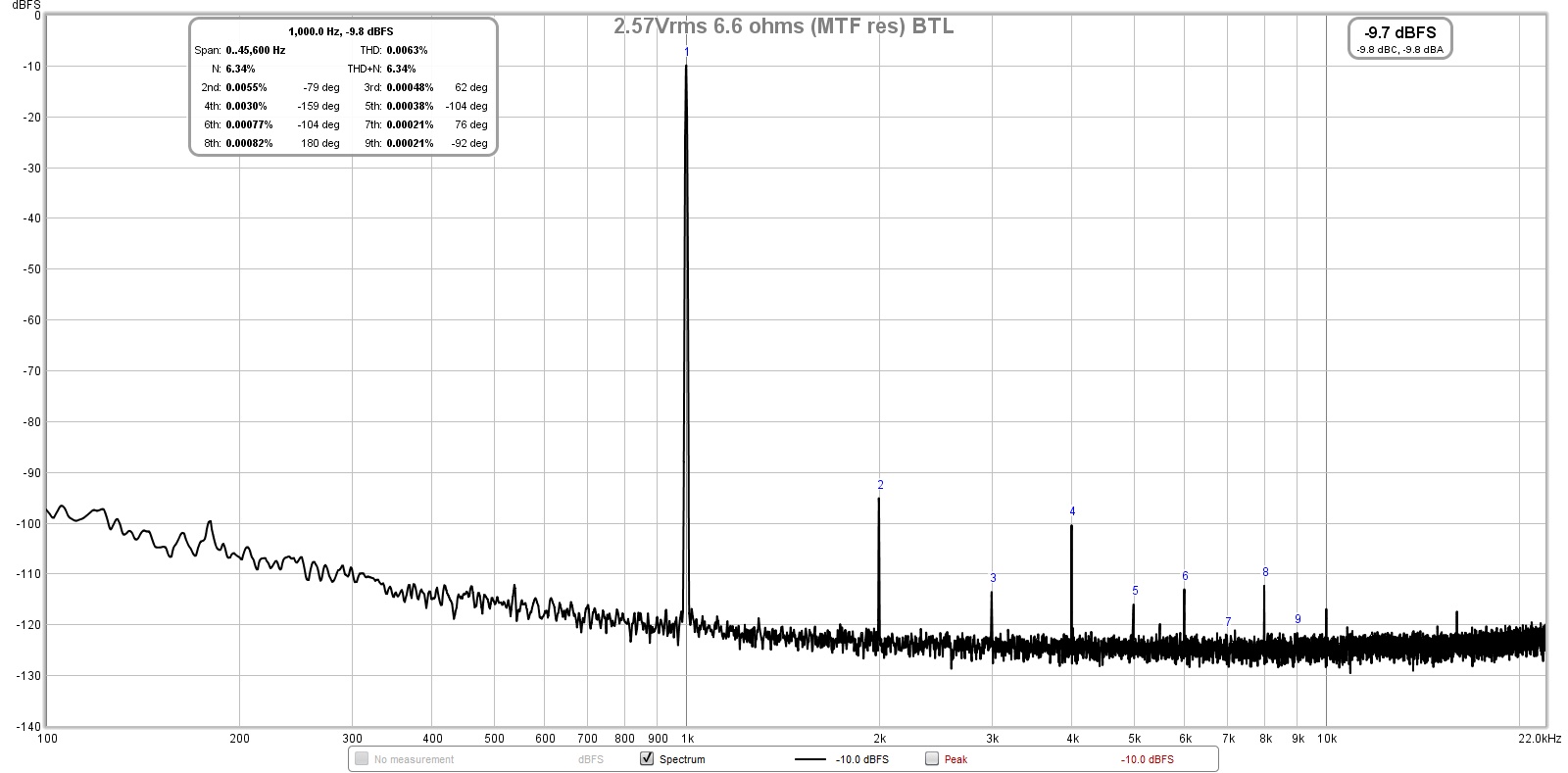
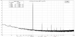
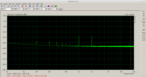
FFT for 2.57 Vrms into 6.6ohms (1W):
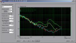
Distortion sweep over frequency at 4W:
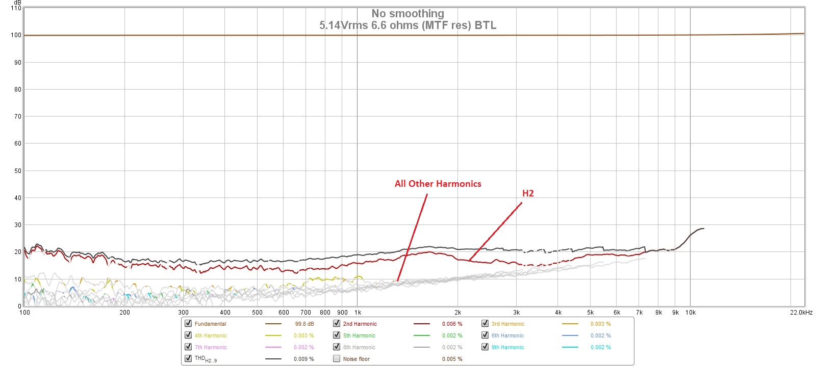
My limited size temporary heatsink only allows lower powers to be tested at present. The amp displays a nice 2nd harmomic dominant profile, as opposed to the 3E and EVM style layouts that exhibit 3rd order dominant harmonic distortion with alternating high/low odd order distortion. This amp exhibits alternating high/low EVEN order distortion. So I think for many people, this may sound better and less fatiguing. A sweep over frequency space shows that the H2 is dominant and quite a bit higher than the rest. Not sure where this is coming from, but for people with propensity for SE Class A amps, this will sound right at home.
Setup:
FFT for 5.14 Vrms into 6.6ohms (4W):
FFT for 2.57 Vrms into 6.6ohms (1W):
Distortion sweep over frequency at 4W:
Attachments

Not bad, but im a bit unsure if you can't do better for K2. From the results in
TPA3255 Reference Design Class D Amp GB
K1: -10dBFS
K2: -95dBFS
K3: -122dBFS
so:
K1/K2: -85dB
K1/K3: 111dB
K1/K3 is very good.
TPA3255 Reference Design Class D Amp GB
Using 6R6 should result in better specs. From your FFT there is:1W into 3R8:
THD: 0.0016%
THD+N: 0.02%
K1: 11.9dBV
K2: -94.22dBV
K3: -89.8dBV
K1/K2: 106.12dBV
K1/K3: 101.7dBV
K1: -10dBFS
K2: -95dBFS
K3: -122dBFS
so:
K1/K2: -85dB
K1/K3: 111dB
K1/K3 is very good.
It’s puzzling that my measurements show a complete flip of the even/odd order dominance. Could the BTL 4-resistor measurement voltage divider be cause of this? I agree that H2 should be lower and seems anomalous relative to the other orders when looking at the sweep.
Attached image shows dual 2ohm 10w resistors. Data above replaces those with 8x 3.3ohm 2w resistors in series/parallel+series for 6.6ohm load.
Attached image shows dual 2ohm 10w resistors. Data above replaces those with 8x 3.3ohm 2w resistors in series/parallel+series for 6.6ohm load.
Attachments
Last edited:
Your setup is not symmetrical as you have 22k on + but 27k on -. I'd also decouple the XLR-IN with additional capacitors like shown here and would no connect GND there.
TPA3255 Reference Design Class D Amp GB
As your soundcard/interface has balanced input, this should work fine.
TPA3255 Reference Design Class D Amp GB
As your soundcard/interface has balanced input, this should work fine.
It was dominant H2 that was the reason for some investigation on my TPA3255 prototype. The culprit was PCB layout - if you aim at H2 levels of -100dB - layout is very critical.
The source of H2 is the supply current feeding the BTL brigde, at this point we have the full wave rectified output signal.
The current loop where it circulates creates considerable H2 magnetic field which couples into any loop of the input stage(s) - consider we are talking about noise voltages in the uV region.
Connect some simple inductor coil with the input of your THD analyzer and go sniffing for H2 field - this might be a revealing experience.
Hi Voltwide,
Here is the layout for the supply to the input power pins. It can’t get much shorter than that if one wants to reduce current loop path. Are you suggesting that this might be source of H2?
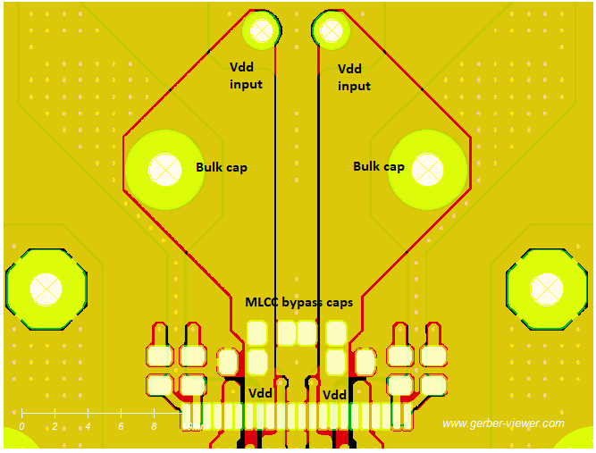
Here is the layout for the supply to the input power pins. It can’t get much shorter than that if one wants to reduce current loop path. Are you suggesting that this might be source of H2?
Do a measurement with/without heatsink and compare harmonic-signature.
1. Is your heatsink grounded? (connected to GND)
1a. If yes, try isolating one side (screw)
1b. If not at all, ground it then follow 1a
2. do you have proper electrical connection between heatpad (TPA3255 case) and heatsink?
2a. If yes, see 1.
2b. If aluminum is anodized, sand it until fully blank, then see 1
Btw. The loop between local PVDD MLCC bypass and bulk cap (GND wise) is not symmetrical with respect to PVDD. This might by critical for the center GND connection.
Here's how the FETs are connected between supplies:
outA: GNDA (41,42); PVDDAB (36,37,38)
outB: GNDBC (33,34); PVDDAB (36,37,38)
outC: GNDBC (33,34); PVDDCD (29,30,31)
outD: GNDD (25,26); PVDDCD (29,30,31)
All of these GNDs are loosely shorted together internally, but one should not rely in the internal short to conduct full current.
It won’t run at all without a heatsink, but I can sand aluminum to remove anodized coating. Will check with continuity meter to see if grounded currently. Screw pads are grounded, might be hard to insulate just one or both. Is your hypothesis that the thermal pad being grounded to both screws is causing the high H2?
I remember problems like this with an old board revision even a bit different.
H2 signature changed with/without heatsink. The problem where somewhat like the GND plane coupled into the heatsink from the center GND connection acting as an antenna. It helped to GND the heatsink properly but isolated one screw-side. (Either by using a plastic one or cutting the thermals around the hole)
I'll have to look for a measurement. One moment please.
BTW. Could you do a crosscoupling test? So suppling signal into Channel A+B (BTL) and measure Channel C+D (BTL). This way we may see it it is related to power supply coupling.
It should run without heatsink up to several watts. Have you looked for oscillation the the in/outputs with a scope when unloaded? Whats the quiescent currents at PVDD? Do you have a thermal imager?
H2 signature changed with/without heatsink. The problem where somewhat like the GND plane coupled into the heatsink from the center GND connection acting as an antenna. It helped to GND the heatsink properly but isolated one screw-side. (Either by using a plastic one or cutting the thermals around the hole)
I'll have to look for a measurement. One moment please.
BTW. Could you do a crosscoupling test? So suppling signal into Channel A+B (BTL) and measure Channel C+D (BTL). This way we may see it it is related to power supply coupling.
It won’t run at all without a heatsink
It should run without heatsink up to several watts. Have you looked for oscillation the the in/outputs with a scope when unloaded? Whats the quiescent currents at PVDD? Do you have a thermal imager?
Last edited:
Ok i found it:
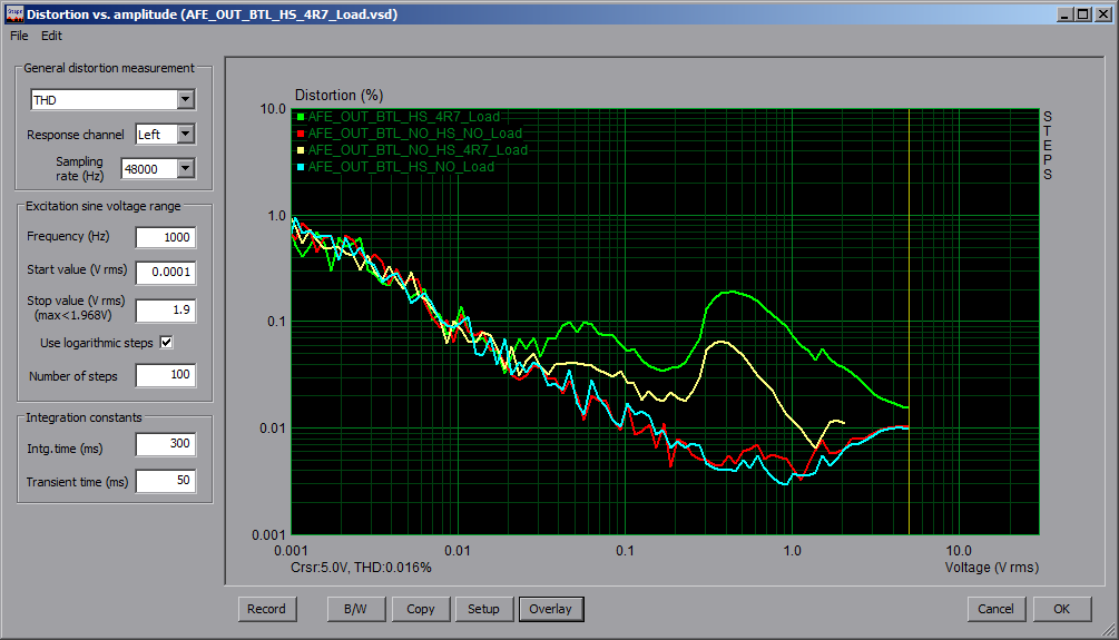
HS = with heatsink
NO_HS = without heatsink
The signals shown are at the TPA3255 inputs (so at the AFE opamps outputs). It might be usefull to check if the "high" K2 is already present at the 3255 inputs.
Voltwide did some EMC probing on the EVM as well.
Quote:
HS = with heatsink
NO_HS = without heatsink
The signals shown are at the TPA3255 inputs (so at the AFE opamps outputs). It might be usefull to check if the "high" K2 is already present at the 3255 inputs.
Voltwide did some EMC probing on the EVM as well.
Quote:
(Translation by deepl.com)I just put the EVM3255 into operation again for fun,
1kHz and about 20W output power, PBTL at Rl=10R.
The magnetic field was recorded using a small, simple wire loop at the end of a shielded cable.
This was located on one of the two large electrolytic capacitors.
k2 field is already detectable with this minimal arrangement!

Well, if the different lines to StarGND form surfaces with each other, then you have the mixed lettuce in the presence of magnetic interference fields.
Minimal loops between related + and - inputs then go BEFORE Star-GND.
Attachments
The photograph of H2 measuring setup gives an imagination of the dimensions. See this tiny loop - at the input of the amp - amplified by 20db at the output - and there you are.
I recollect that one idea was creating two small and physical identical loops around the bulk caps that should compensate each other.
And keep any input loops extremely small...
I recollect that one idea was creating two small and physical identical loops around the bulk caps that should compensate each other.
And keep any input loops extremely small...
The plot distortion/heatsink plot in TPA3255 Reference Design Class D Amp GB
shows three things:
1: Without a load there will be no problems with THD
2: With a load connected, there's EMC coupling alone
3: With a heatsink, EMC coupling is amplified/even worse
Out of curiosity, replace all 10uH filter inductors for your low voltage supply rails with 10R resistors and measure again. (They not always make things better)
Ok, thanks for the tips guys.
I did the following:
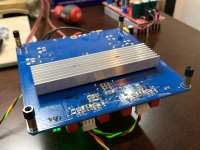
1. drill and tap a proper heatsink and sanded aluminum to ensure proper grounding. This helped a little as it took THD from 0.0091% to 0.0084%.
2. I made the recomended symmetric attenuator suggested as Voltwide used with 9k1-2k-9k1 and 1uF film caps on each end to decouple the DC. No GND connection from XLR pin on Focusrite - just balanced pins 2 and 3.
Proper grounded heatsink with drilled and tapped holes:

Setup:
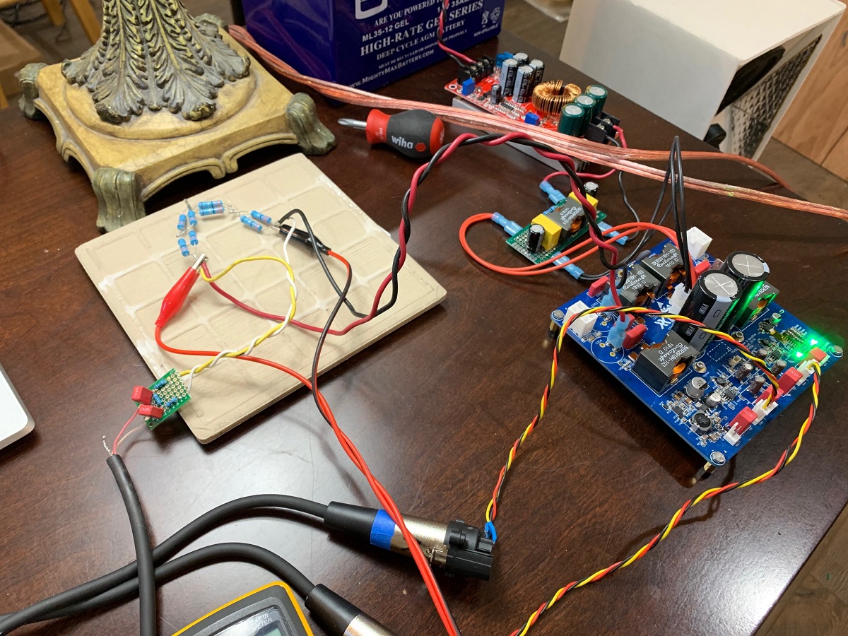
Closeup of symmetric attenuator:

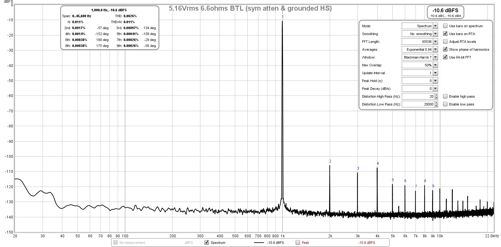
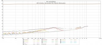
Same measurement at 5.16Vrms now shows much improved THD in the 0.0026% and much lower H2 but still H2 higher than H3 by a tiny bit. Still alternating hi/low even/odd vs odd/even as on previous 3E amp. I like how it looks a lot now. The measurement resistor divider affects the THD if not done symmetricaly.
FFT for 5.16Vrms into 6.6ohms (4W) now with 0.0026% THD:
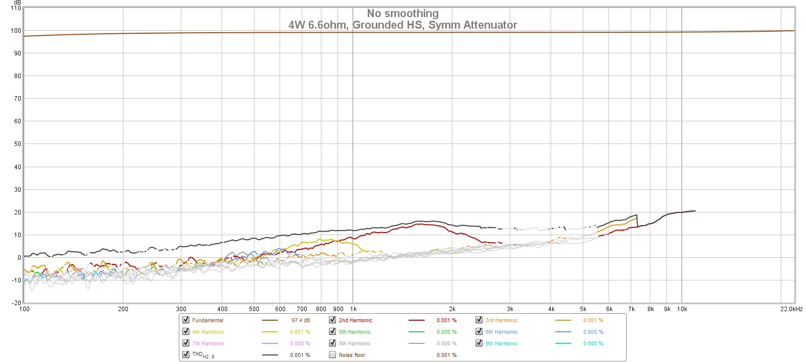
Sweep at 4W into 6.6ohms:
I actaully like where how the H2 is slightly higher than the H3 and the behavior is even/odd dominant.
Is current loop still a problem here? I am happy with it now.
I did the following:
1. drill and tap a proper heatsink and sanded aluminum to ensure proper grounding. This helped a little as it took THD from 0.0091% to 0.0084%.
2. I made the recomended symmetric attenuator suggested as Voltwide used with 9k1-2k-9k1 and 1uF film caps on each end to decouple the DC. No GND connection from XLR pin on Focusrite - just balanced pins 2 and 3.
Proper grounded heatsink with drilled and tapped holes:
Setup:
Closeup of symmetric attenuator:
Same measurement at 5.16Vrms now shows much improved THD in the 0.0026% and much lower H2 but still H2 higher than H3 by a tiny bit. Still alternating hi/low even/odd vs odd/even as on previous 3E amp. I like how it looks a lot now. The measurement resistor divider affects the THD if not done symmetricaly.
FFT for 5.16Vrms into 6.6ohms (4W) now with 0.0026% THD:
Sweep at 4W into 6.6ohms:
I actaully like where how the H2 is slightly higher than the H3 and the behavior is even/odd dominant.
Is current loop still a problem here? I am happy with it now.
Attachments
-
 TPA3255-BTL-Test-Setup-Symm-Atten-Gnd-HS.jpg436.3 KB · Views: 3,126
 -
 TPA3255-BTL-Test-Setup-Symm-Atten-Closeup.jpg385.6 KB · Views: 2,988
 -
 TPA3255-rev0b-5.14Vrms-6.6ohms-BTL-FFT-HS-Grounded-Symm-Atten-5.jpg235.6 KB · Views: 3,084
 -
 TPA3255-rev0b-5.14Vrms-6.6ohms-BTL-Sweep-HS-Grounded-Symm-Atten-5.jpg176.8 KB · Views: 1,169
 -
 TPA3255-proper-heatsink.jpg360.5 KB · Views: 1,206
Last edited:
With this now working setup i'd explore the influence of the heatsink mounting and grounding. What happens if heatsink is isolated/grounded, what happens if thermal-pad is electrical connected to grounded heatsink, or not. Do a crosscouple test to see how much is coupling into the other channel.
Another thing that worries me is that your 3255 is not running without heatsink at all. So quiescent current and hunting for possible oscillation is a good thing to do.
H1/H2 looks quite good now with 95dB but could be better as shown. Your board is made so much better pcb-wise but still lacks 10dB H1/H2 compared to our cheap 1oz. copper board.
- Home
- Group Buys
- TPA3255 Reference Design Class D Amp GB