Focusrite 2i4 2nd gen. Although Focusrite Solo 2nd gen works well too. I hear that a gen 3 is out now.
More details on how to do measurements here:
Howto - Distortion Measurements with REW
More details on how to do measurements here:
Howto - Distortion Measurements with REW
Yes. But you may take into account the contribution of additional circuitry supplied from that rail.
I could mount a precision 0.1ohm shunt resistor across the solder bridge pads for the supply to the ancillary 15v DC-DC converter - I could get a sense of current used there. Or even solder two test clip posts and connect alligator clips in line with Fluke ammeter.
I did the quiescent current test with both my amp and the 3E amp using a Fluke 115 meter in series between the 51.0v DC-DC converter PSU (after my CLC filter) and the power input to the amp. Load condition was same 6.6ohm resistor bank and 5.16Vrms.
3E AMP:
3E amp no load was 0.149A or 7.60W quiescent dissipation.
3E amp with 5.16Vrms into 6.6ohms was 0.235A or 86mA current difference. 86mA x 51v = 4.386W. 5.16Vrms into 6.6ohms is 4.03W, so ancillary stuff is 356mW (seems about right).
Present JPS64 Amp:
No load was 0.118A or 6.02W quiescent
With 5.16Vrms into 6.6ohm load was 0.204A or 86mA difference intoload for same 4.386W, and ancillary is same 356mW.
It would seem that the present amp has less quiescent current than 3E. Maybe 3E amp can't run without HS either?
From the datasheet for 51v supply, IVdd (12v) is 30mA, Igate (12v) is 44mA, and IPvdd (51v) is 24mA. Converting the 12v currents for IVdd and Igate and adding together I get 7.05mA + 10.3mA + 24mA = 41.8mA per channel, x 2 channels is 84mA. Accounting for some losses in the DC-DC conversion, this is very close to the 118mA quiescent current I measure.
What do you guys get for quiescent current?
Pro !
Really professional PCB and great result!
Is this the same measurement setup as with the 3eAudio boards?
Really professional PCB and great result!
Is this the same measurement setup as with the 3eAudio boards?
Hi Piersma,
Thanks! The setup is the same except for the 3E, I used a big 100W 8ohm resistor dummy load for high power testing, and I had an asymmetric voltage divider. For the above tests, I used the symmetric voltage divider as suggested by Voltwide, and through my own experimentation, I found that qnty 8x 2w 1% metal thin film resistors in series/parallel provides a nice low-distortion 6.6ohm load. In general, I have found that metal thin film resistors used for dummy loads, add less harmonic distortion than wirewounds. So I repeated the measurements with the same exact rig and same setting of 5.14Vrms (4W into 6.6ohms) on the 3E amp as I was already looking at the quiescennt current.
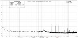
Here is the FFT for 5.16Vrms into 6.6ohms, the THD went down from the previous measurement, but still higher than the present amp designed in this thread (0.0046% THD), also note that the harmonic distortion is 3rd order dominant:

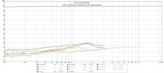
Here are the harmonic distortion components as a function of frequency, the overall behavior is very similar to the present amp from this thread:

Btw, O-scope examination of signals from the 3E amp and the present amp in this thread show no oscillations. Residual 450kHz hash from the Class D switching is present at low levels but, that of course, is an inevitable part of Class D amps.
As the test setup is identical in both cases, the lower levels of distortion in the present amp vs the 3E amp can only be attributed to layout and component selections. The Coilcraft SER inductors may have some nice benefits, as well as the extensive use of all metal thin film SMT resistors (no metal oxide thick film resistors were used), and quality NP0/C0G capacitors where it mattered.
Although it seems I am still not achieving the circa 10dB lower THD values that Dr Mord and Voltwide were achieving in their amps at similar conditions, I am pretty happy with the current result given that the slightly higher THD is offset by fact that it is 2ns order and even order dominant.
Thanks! The setup is the same except for the 3E, I used a big 100W 8ohm resistor dummy load for high power testing, and I had an asymmetric voltage divider. For the above tests, I used the symmetric voltage divider as suggested by Voltwide, and through my own experimentation, I found that qnty 8x 2w 1% metal thin film resistors in series/parallel provides a nice low-distortion 6.6ohm load. In general, I have found that metal thin film resistors used for dummy loads, add less harmonic distortion than wirewounds. So I repeated the measurements with the same exact rig and same setting of 5.14Vrms (4W into 6.6ohms) on the 3E amp as I was already looking at the quiescennt current.
Here is the FFT for 5.16Vrms into 6.6ohms, the THD went down from the previous measurement, but still higher than the present amp designed in this thread (0.0046% THD), also note that the harmonic distortion is 3rd order dominant:
Here are the harmonic distortion components as a function of frequency, the overall behavior is very similar to the present amp from this thread:
Btw, O-scope examination of signals from the 3E amp and the present amp in this thread show no oscillations. Residual 450kHz hash from the Class D switching is present at low levels but, that of course, is an inevitable part of Class D amps.
As the test setup is identical in both cases, the lower levels of distortion in the present amp vs the 3E amp can only be attributed to layout and component selections. The Coilcraft SER inductors may have some nice benefits, as well as the extensive use of all metal thin film SMT resistors (no metal oxide thick film resistors were used), and quality NP0/C0G capacitors where it mattered.
Although it seems I am still not achieving the circa 10dB lower THD values that Dr Mord and Voltwide were achieving in their amps at similar conditions, I am pretty happy with the current result given that the slightly higher THD is offset by fact that it is 2ns order and even order dominant.
Attachments

Last edited:
Dr Mord,
I just looked carefully at the plot:

So it looks like if one could not have a heatsink, it is lower distortion? Is that why you say to make one bolt non-conductive to prevent a current loop through the heatsink path? We can do that on the final spin, but to test it, I could drill out the hole and add a nylon shoulder washer - same as used on a TO-220 local heatsink bolt.
I just looked carefully at the plot:
So it looks like if one could not have a heatsink, it is lower distortion? Is that why you say to make one bolt non-conductive to prevent a current loop through the heatsink path? We can do that on the final spin, but to test it, I could drill out the hole and add a nylon shoulder washer - same as used on a TO-220 local heatsink bolt.
Not directly, but it shows that you can have increased THD just by bad grounding and/or layout regarding ground loops, signal loops, ground planes etc.
These issues where fixed at a later layout.
All those tests I mentioned can be a base for further discussion as Voltwide and me did really extensive measurements and tests regarding almost every aspect with these chips.
Crosschecking from one channel to another will clearly show problems with supply coupling.
Cross checking is same as cross talk measurement? Excite Ch1 while looking at output of Ch 2, etc?
Correct. You can even probe the supply rails with DC decoupling at high output power for an indication.
I'd also take a measurement at the opamp outputs (so to speak 3255 inputs)
I'd also take a measurement at the opamp outputs (so to speak 3255 inputs)
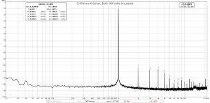
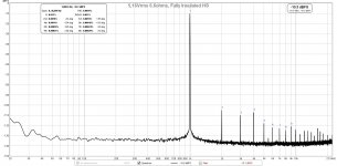
I tested the effect of grounded vs non-grounded heatsink and effect of one or both bolts insulated.
Here is photo of a ceramic inuslator spacer being installed on the TPA3255:

Here is heatsink fully grounded at the TPA3255 powerpad and at the two clamp bolts:

Here is one of the bolts insulated:

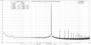
Here is both bolts insulated and powerpad insulated with a ceramic spacer:

So it seems that either fully insulated or fully grounded is the same, but partial insulated bolts has higher distortion. I will run with fully grounded config (default).
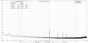
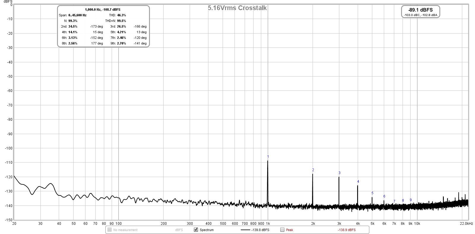
Here is crosstalk from one channel (excited) to the other (not excited):

Here is photo of a ceramic inuslator spacer being installed on the TPA3255:
Here is heatsink fully grounded at the TPA3255 powerpad and at the two clamp bolts:
Here is one of the bolts insulated:
Here is both bolts insulated and powerpad insulated with a ceramic spacer:
So it seems that either fully insulated or fully grounded is the same, but partial insulated bolts has higher distortion. I will run with fully grounded config (default).
Here is crosstalk from one channel (excited) to the other (not excited):
Attachments
-
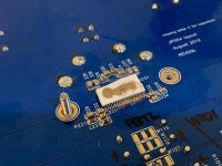 Photo-ceramic-spacer-TPA3255.jpg374 KB · Views: 1,043
 -
 TPA3255-3E-amp-5.16Vrms-6.6ohms-BTL-FFT-HS-Fully-Grounded-6.jpg202.4 KB · Views: 1,027
 -
 TPA3255-3E-amp-5.16Vrms-6.6ohms-BTL-FFT-HS-Grounded-Rt-bolt-Insulated-Symm-Atten-5.jpg203.6 KB · Views: 1,033
 -
 TPA3255-3E-amp-5.16Vrms-6.6ohms-BTL-FFT-HS-Grounded-Both-bolt-Insulated-Symm-Atten-5.jpg201.3 KB · Views: 91
 -
 TPA3255-3E-amp-5.16Vrms-6.6ohms-BTL-FFT-HS-Fully-Insulated-6.jpg200.3 KB · Views: 1,014
 -
 TPA3255-3E-amp-5.16Vrms-6.6ohms-BTL-FFT-HS-Fully-Insulated-6-Crosstalk.jpg193.4 KB · Views: 1,097
Last edited:
Now that we have high resolution test equipment we discover all these tiny imperfections in reality...
You may try to reduce input loop:
Disconnect the inputs of the passive channel
Test with open input pins.
Shorten input pins either with some MLCC or directly by a solder blob.
In case the residual THD is unaffected this maybe crosstalk inside the chip.
You may try to reduce input loop:
Disconnect the inputs of the passive channel
Test with open input pins.
Shorten input pins either with some MLCC or directly by a solder blob.
In case the residual THD is unaffected this maybe crosstalk inside the chip.
Is this crosstalk at 4W?
The same measurements should be done ne for the AFE (to see where to optimize).
The same measurements should be done ne for the AFE (to see where to optimize).
Thanks for all the suggestions.
TBH, I am quite happy with the level of THD and the profile. I would rather have this profile, then to reduce THD by -10dB and have third order dominant. It may actually be a desirable "feature" of this particular layout.
I do have a question, when doing the tests, I am only connecting the load to one side and the other side has no load connected, although not being driven. Is this bad, I have heard that Class D amps always need to be connected to a load - will make a second dummy load resistor to connect and see if that might help.
Yes
I did, it went down maybe -1dB, almost imperceptible.Disconnect the inputs of the passive channel
Where does one apply the test tone then? Or just looking at background noise?Test with open input pins.
I am using 10uF 35v Elna Silmic II electrolytics between the opamp and TPA, I wonder if the larger cap body could be acting as an antenna for pickup?Shorten input pins either with some MLCC or directly by a solder blob.
TBH, I am quite happy with the level of THD and the profile. I would rather have this profile, then to reduce THD by -10dB and have third order dominant. It may actually be a desirable "feature" of this particular layout.
I do have a question, when doing the tests, I am only connecting the load to one side and the other side has no load connected, although not being driven. Is this bad, I have heard that Class D amps always need to be connected to a load - will make a second dummy load resistor to connect and see if that might help.
Is this crosstalk at 4W?
Yes
Last edited:
A dummy load on the idle channel does no harm, but is not really necessary.Thanks for all the suggestions.
I did, it went down maybe -1dB, almost imperceptible.
Where does one apply the test tone then? Or just looking at background noise?
I am using 10uF 35v Elna Silmic II electrolytics between the opamp and TPA, I wonder if the larger cap body could be acting as an antenna for pickup?
TBH, I am quite happy with the level of THD and the profile. I would rather have this profile, then to reduce THD by -10dB and have third order dominant. It may actually be a desirable "feature" of this particular layout.
I do have a question, when doing the tests, I am only connecting the load to one side and the other side has no load connected, although not being driven. Is this bad, I have heard that Class D amps always need to be connected to a load - will make a second dummy load resistor to connect and see if that might help.
Yes
Hi Voltwide,
What levels of crosstalk are you getting on your best implementation? Also, are my quiescent currents ok?
In my experience, -99dB crosstalk is quite respectable for a stereo monolithic chip. By the very nature of the output devices being mounted on the same die makes it very had to be as good as dual monoblocks. Dual PBTL is the way to go for zero crosstalk.
- Home
- Group Buys
- TPA3255 Reference Design Class D Amp GB