The Mouser order for the BOM arrived. About 70 bags. Good thing they are labeled to match the component number/silkscreen.
every time i make a mouser order i shudder at the amount of plastic involved especially when a single smd part comes in full size bag.
very much looking forward to seeing your measured results
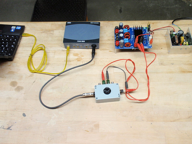
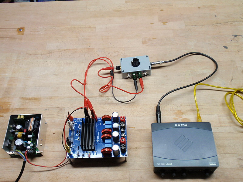
Please describe your test setup in detail. Do you measure BTL bridge with a symm input analyzer? Measuring only one half bridge gives pretty bad THD numbers. I prefer measuring with some 24bit soundcard like emu-0202 feeding the btl-output through a symm 30dB-attenuator to the symm line input driving its ADC between -20~-10 dBFS.
And yes, a preceeding loopback measurement might be insightful.
Edit: I see you did a loopback measurement with the focusrite, the result is quite similar to my observations here.
I managed to build a TPA PBTL board where the resolution of the soundcard nearly reached its limits, so there is room for improvement.
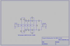
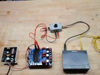
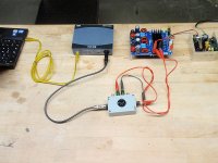
The BTL output of amp is connected to dummy load resistor. The same load is connected to 22k+2k divider for 11:1 attenuation. The divider output is fed to the balanced input (XLR pins 2 & 3) of the line input of Focusrite 2i4 with “pad”button pushed to further attenuate signal. Input is adjusted to between -10dB and -20dB full scale with gain knob on front panel. Using ASIO 24bit and 96kHz sampling. I found way too much 60Hz and 120Hz/180Hz/ and harmonics pickup even though nothing was connected to mains. I then connected pin 1 (GND of Focusrite) of XLR jack to -ve pin 3. That got rid of mains noise and main signal peaks stayed the same. Everything is battery powered from amp to laptop and Focusrite.
Cable from 11:1 attenuator to Focusrite was a commercially available shielded two conductor XLR microphone cable cut in half with flying leads pins 2 and 3 connected to dummy load.
Source is Akitika 2ppm 1kHz oscillator feeding the 3E amp in SE mode via RCA jack. Source is powered by 2x 9v batteries.
Details of how to use REW and soundcard for distortion measurements here:
Howto - Distortion Measurements with REW
Last edited:
Thanks for your description of the setup. I want to stress the requirement that each bridge outputs A and B should have their own attenuator before entering the symmetrical soundcard input.
GND connection between soundcard and amp is granted by the asymmetric input channel exclusively. No output grounding.
The small grey box on the left side of the picture Doctormord just presented is a 2 channel version with steps -6 -12 -18 -24 -30 -36dB of attenuation. Most of the time it is set to -30 or -36dB feeding an EMU-tracker (without input pad).
Last edited:
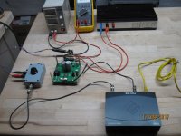
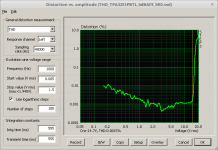
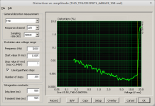
I'll post some plots of old measurements on a very old design (3255) to show influence of different setups. This layout suffered from bad grounding and big conduction loops at the output. Esspecially the "GND notch" at the 3255 between the outputs had a huge impact:
Power supply:
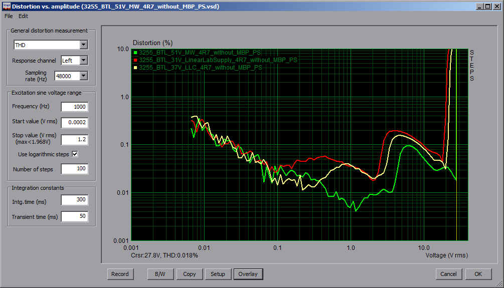
Lab supply is 30V/5A
MW is Meanwell LRS-350
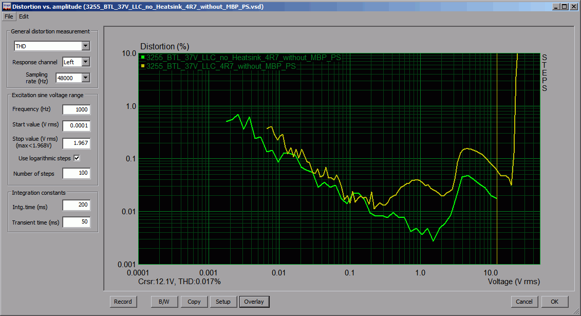
LLC is Voltwide 50V LLC Converter
Heatsink:
How to do a good/clean test setup (by Voltwide):
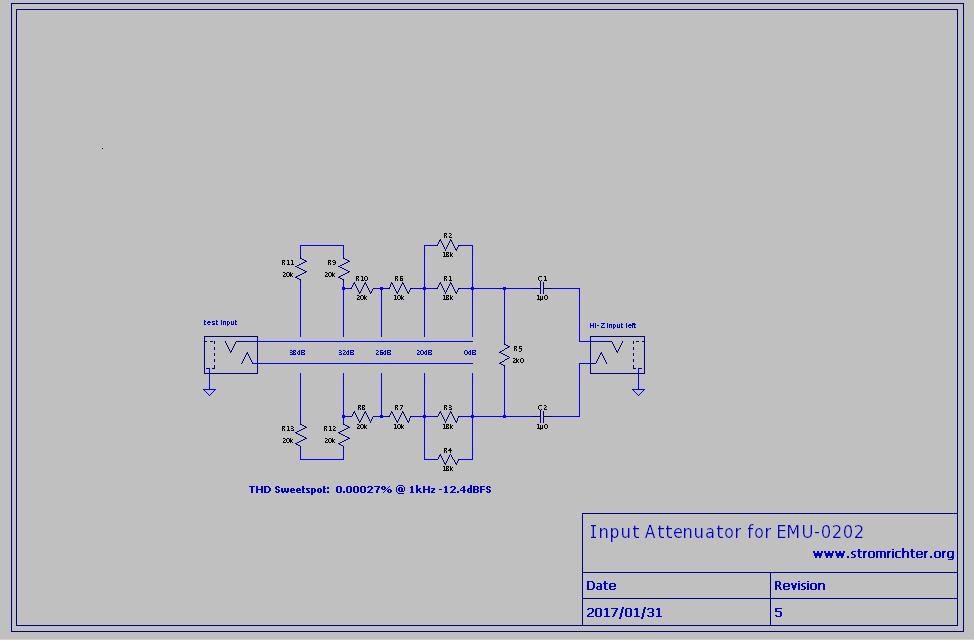
Possible attentuator (by Voltwide):
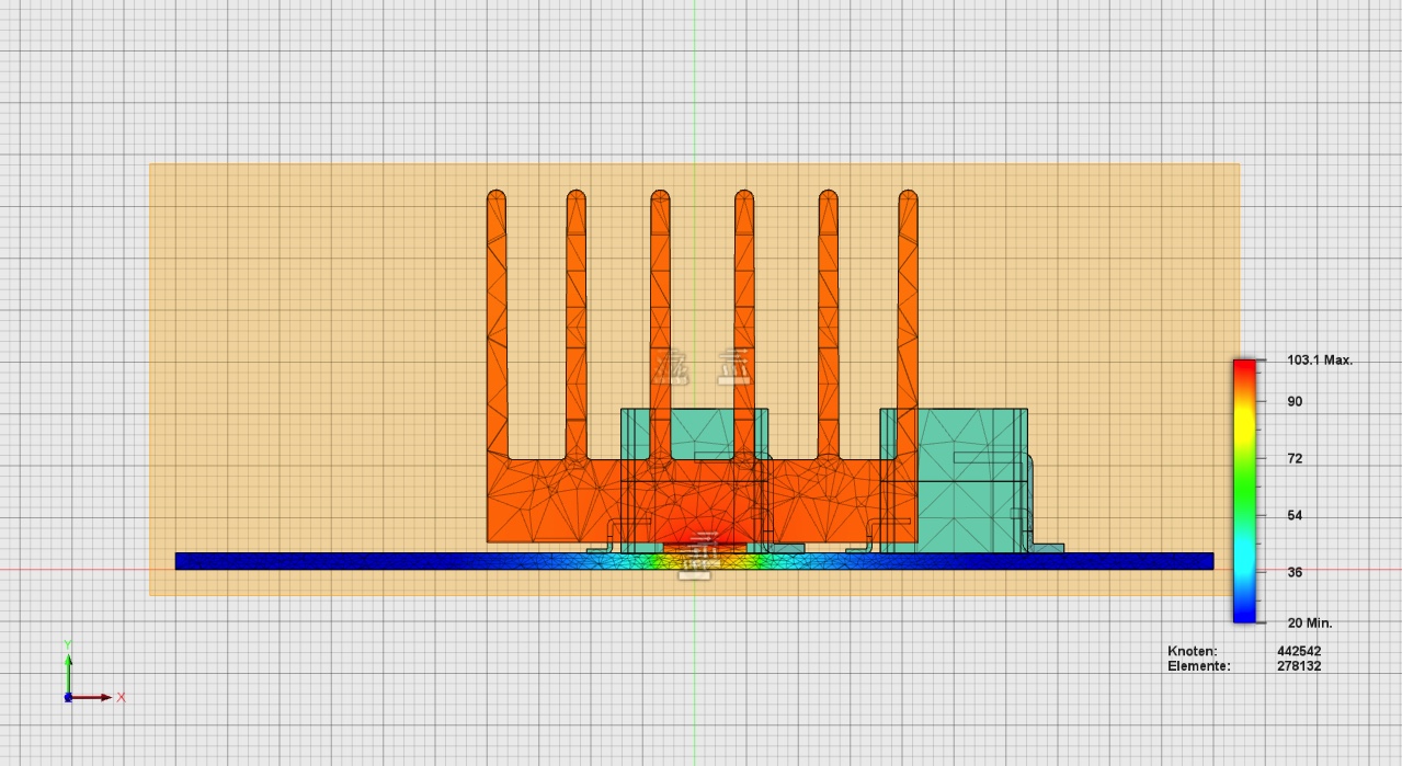
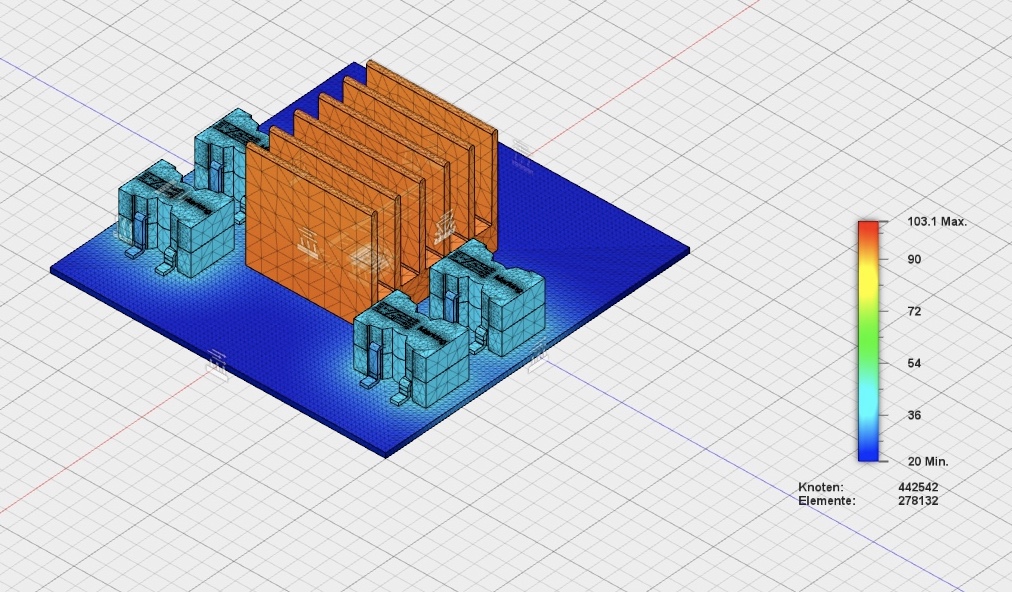
Actually totally OT, but attached for reference, we once simulated a steady 10W dissipation from TPA3255 into an "SK189 37,4 SA" (Which is 4K/W in this length) heatsink + additional 0.5W inductor loss.
Power supply:
Lab supply is 30V/5A
MW is Meanwell LRS-350
LLC is Voltwide 50V LLC Converter
Heatsink:
How to do a good/clean test setup (by Voltwide):
Possible attentuator (by Voltwide):
Actually totally OT, but attached for reference, we once simulated a steady 10W dissipation from TPA3255 into an "SK189 37,4 SA" (Which is 4K/W in this length) heatsink + additional 0.5W inductor loss.
Attachments
-
 Bild 21.10.16 um 14.20.jpg316.5 KB · Views: 1,242
 -
 fullsizeoutput_1c1.jpeg264.5 KB · Views: 1,211
 -
 PSU_BTL.png48.3 KB · Views: 1,266
 -
 3255_BTL_37V_LLC_4R7_Heatsink_noHeatsink.png19.6 KB · Views: 1,259
 -
 att.png10.5 KB · Views: 5,584
 -
 evm3255_pvcc_test_no_load_P2160001.JPG148.2 KB · Views: 3,492
 -
 evm3255_pvcc_test_no_load_P2160003.JPG150 KB · Views: 1,831
Thanks for posting the above, Dr Mord. Looks like you were also getting similar 0.01% to 0.02% THD in the mid to high power ranges. Power supply appears to make a big difference.
Do you have any FFTs at 1kHz excitation so that I can see if there are any egregious harmonics that I should not be getting?
I can redo another measurement with a swept excitation vs power to see what the response looks like. That has to be manually done in REW though.
Do you have any FFTs at 1kHz excitation so that I can see if there are any egregious harmonics that I should not be getting?
I can redo another measurement with a swept excitation vs power to see what the response looks like. That has to be manually done in REW though.
It is an intimidating box full of bags 🙂
Yes, even more so if the bags were unlabeled relative to BOM component number. 😉
Well there are 2 zeros missing behind the decimal point😉Thanks for posting the above, Dr Mord. Looks like you were also getting similar 0.01% to 0.02% THD in the mid to high power ranges. Power supply appears to make a big difference.
Dr Mord and me obtained pretty good results with an unregulated LLC smps, so I would not over-estimate the power supply in an TPA3255 application.
Thanks for posting the above, Dr Mord. Looks like you were also getting similar 0.01% to 0.02% THD in the mid to high power ranges. Power supply appears to make a big difference.
These measurements are just for comparison and not meant for the final implementation. Do NOT bench against these.
The very best results where achieved by Voltwide with its 3251 PBTL (Prefilter) and PFFB.
into 5R0:
into 10R0:
Spectrum at 4Vrms into 5R0:
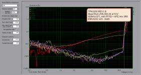
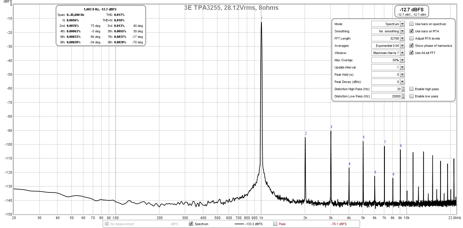
Our latest 3255 Rev1.B board (shown here: TPA3255 / TPA3251 / TPA3245 Rev.1B Final – #360customs) does perform like shown in the following plot:
This is with an unoptimized PFFB into 3R8. Due to lack of time no more optimization where done. 🙂
The 1% THD is hit at about 28Vrms (The bottom plot labeling is wrong due to foldback) which translates to 206W into 3R8. There's one difference between all these boards and the EVM - they're 1oz. copper not 2oz like the EVM.
Attachments
Last edited:
So what can be said for the 3255 Rev1B at 1kHz:
1W into 3R8:
THD: 0.0016%
THD+N: 0.02%
K1: 11.9dBV
K2: -94.22dBV
K3: -89.8dBV
K1/K2: 106.12dBV
K1/K3: 101.7dBV
10W into 3R8:
THD: 0.0016%
THD+N: 0.013%
K1: 16dBV
K2: -90.4dBV
K3: -82.5dBV
K1/K2: 106.4dBV
K1/K3: 98.5dBV
100W into 3R8:
THD: 0.0039%
THD+N: 0.046%
K1: 25.9dBV
K2: -68.4dBV
K3: -65.4dBV
K1/K2: 94.3dBV
K1/K3: 91.3dBV
K1 is th fundamental, K2/K3 the harmonics, K1/K2 is the difference between those two.
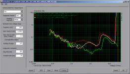
From the plot above (yellow line 1kHz), the amp is below 0.005% between 0.5V and 25Vrms which translates to 0.066W - 165W into 3R8.
1W into 3R8:
THD: 0.0016%
THD+N: 0.02%
K1: 11.9dBV
K2: -94.22dBV
K3: -89.8dBV
K1/K2: 106.12dBV
K1/K3: 101.7dBV
10W into 3R8:
THD: 0.0016%
THD+N: 0.013%
K1: 16dBV
K2: -90.4dBV
K3: -82.5dBV
K1/K2: 106.4dBV
K1/K3: 98.5dBV
100W into 3R8:
THD: 0.0039%
THD+N: 0.046%
K1: 25.9dBV
K2: -68.4dBV
K3: -65.4dBV
K1/K2: 94.3dBV
K1/K3: 91.3dBV
K1 is th fundamental, K2/K3 the harmonics, K1/K2 is the difference between those two.
From the plot above (yellow line 1kHz), the amp is below 0.005% between 0.5V and 25Vrms which translates to 0.066W - 165W into 3R8.
So what can be said for the 3255 Rev1B at 1kHz:
1W into 3R8:
THD: 0.0016%
THD+N: 0.02%
K1: 11.9dBV
K2: -94.22dBV
K3: -89.8dBV
K1/K2: 106.12dBV
K1/K3: 101.7dBV
10W into 3R8:
THD: 0.0016%
THD+N: 0.013%
K1: 16dBV
K2: -90.4dBV
K3: -82.5dBV
K1/K2: 106.4dBV
K1/K3: 98.5dBV
100W into 3R8:
THD: 0.0039%
THD+N: 0.046%
K1: 25.9dBV
K2: -68.4dBV
K3: -65.4dBV
K1/K2: 94.3dBV
K1/K3: 91.3dBV
K1 is th fundamental, K2/K3 the harmonics, K1/K2 is the difference between those two.
From the plot above (yellow line 1kHz), the amp is below 0.005% between 0.5V and 25Vrms which translates to 0.066W - 165W into 3R8.[/QUOTE
did the universal AFE add better performance or was it more about adding more functionality?
did the universal AFE add better performance or was it more about adding more functionality?
This is with the "Universal AFE" module. The intend was/is to be flexible at the input stage. Trying out a different AFE is easy as only the AFE module needs to be changed. (I.e. something around the LMP8350)
(Or implementing some DSP stuff right into the AFE.)
With 0.005% THD I wouln't call the actual perfomance "bad". 😀 (As this is measured without any "magic" AES brickwall filter at a mediocre power-supply).
Btw. I'm still using the red boards (like you build) for my mobile soundbikesystem.
Fresh footage here: Masa Critica Habana - Foro Public Group | Facebook
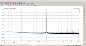
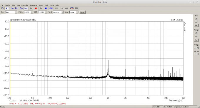
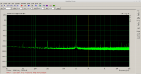
This harmonic profile resembles what I measured (especially the alternative even odd orders height after H2 and dominant H3) so I know that it wasn’t my setup that wasn’t injecting all those higher orders into it. Mine seems to have higher THD but this is 100wrms into 8ohms not 4wrms into 4ohms:
Last edited:
Thanks for posting the above, Dr Mord. Looks like you were also getting similar 0.01% to 0.02% THD in the mid to high power ranges. Power supply appears to make a big difference.
Do you have any FFTs at 1kHz excitation so that I can see if there are any egregious harmonics that I should not be getting?
I can redo another measurement with a swept excitation vs power to see what the response looks like. That has to be manually done in REW though.
You can do an automated sweep vs power with ARTA/STEPS
hi mord
sorry cat jumped on keyboard.
i loved the red board i built one for me and one for my bro unfortunately i was parted from my amp(robbed) and my brother wont sell me his back.
iv built mod 86 since and love it i just dont know if im ...in love with it if you get me.
so want another 3255 board to build just to check my first impressions maybe i do prefer class d?
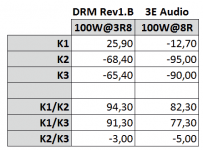
If we compare the numbers from post #132 with the plot data in #136
it looks like the performance of the 3e-audio board is "much" worse"..
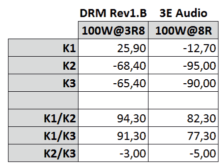
This difference in numbers (K1/K2, K1/K2, K2/K3) would even be greater if measurement where done at 8R compared to 3R8. If im not wrong K1/K2 at 94.3 and 82.3 would translate to 0.002% vs. 0.008 in THD.. (One could say this difference is easily within measurement uncertainty)
Thumbs up for the cat. 🙂
it looks like the performance of the 3e-audio board is "much" worse"..
This difference in numbers (K1/K2, K1/K2, K2/K3) would even be greater if measurement where done at 8R compared to 3R8. If im not wrong K1/K2 at 94.3 and 82.3 would translate to 0.002% vs. 0.008 in THD.. (One could say this difference is easily within measurement uncertainty)
hi mord
sorry cat jumped on keyboard.
Thumbs up for the cat. 🙂
Attachments
Last edited:
- Home
- Group Buys
- TPA3255 Reference Design Class D Amp GB